Skip to main content
Installing the v6 board
Three known problems
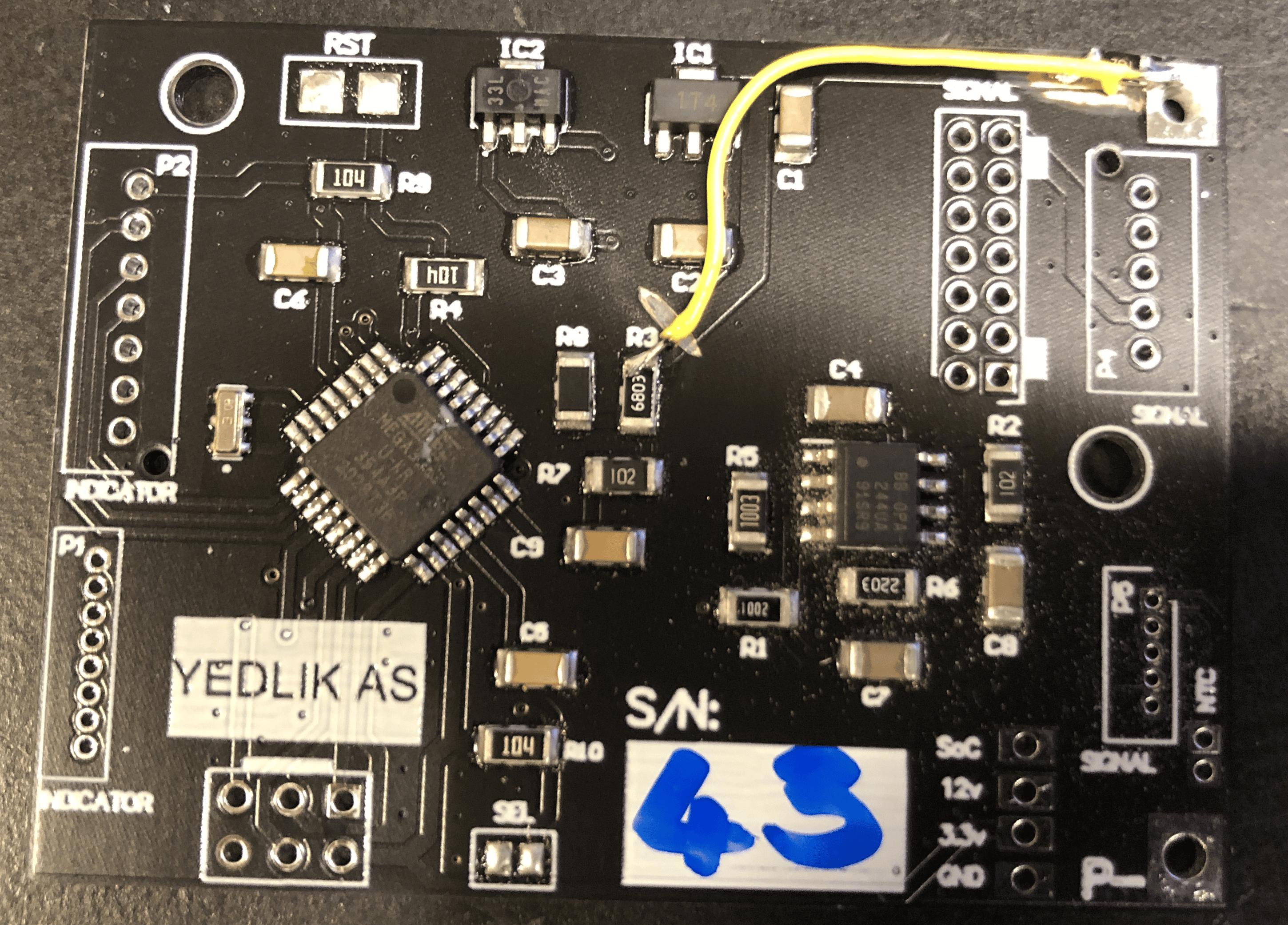
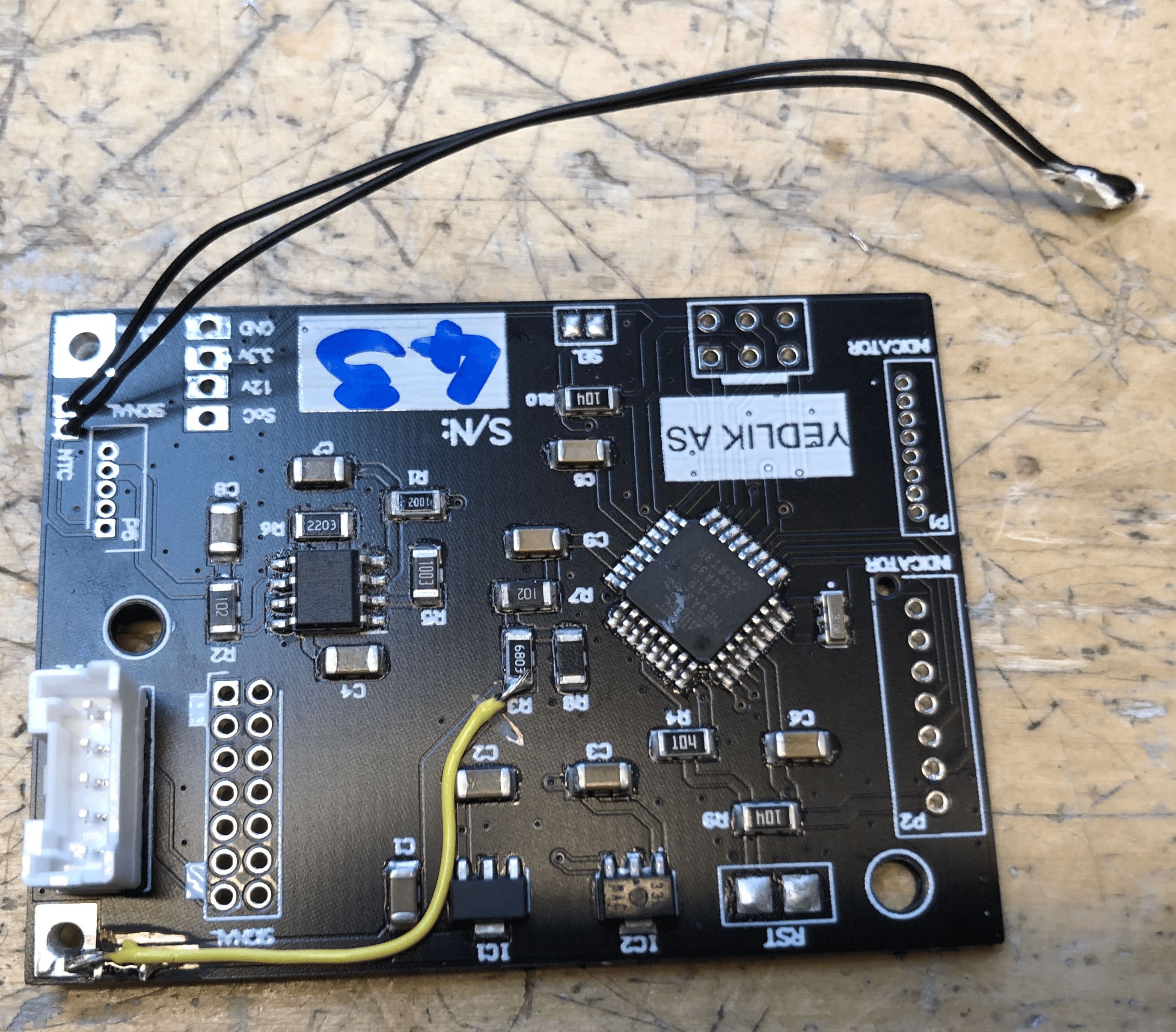
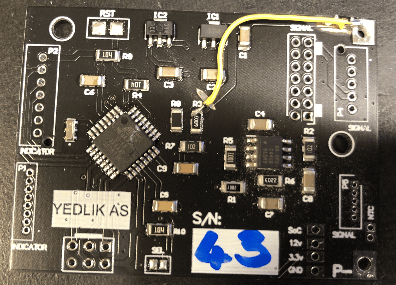
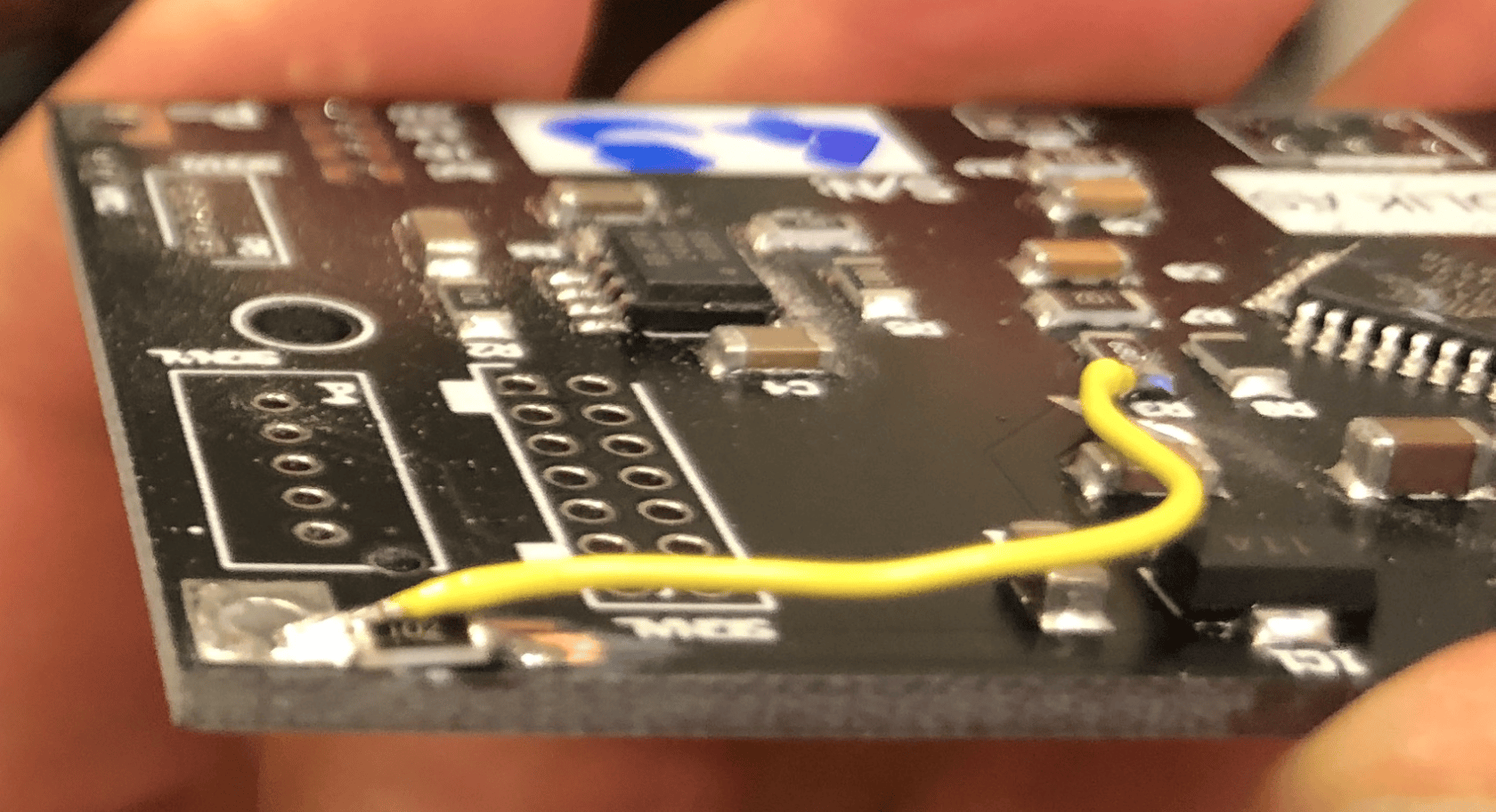
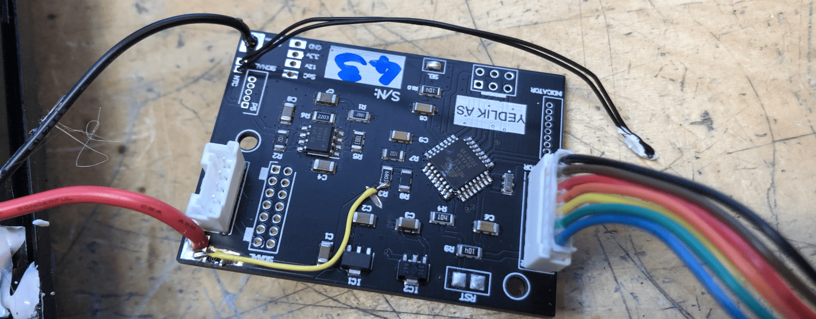
- The ZXTR2012Z voltage regulator cannot handle the battery voltage suddenly appearing on its input without an external current limiting resistor.
- Any resistor would be fine, I used 1k in a 1206 package.
- The voltage divider of the sense must be still exposed to the full input voltage!
- This issue is likely to affect Yamaha boards too!
- Maybe it would be easier to use a low (10 Ohm?) resistor - if it does not blow, there is no need for the bypass, as the voltage drop would be so small (10 Ohm * 1 mA = 10mV)
- The 3rd pin of the 5-pin signal connector (used on the 'white' BMSs) is not connected to the NTC
- This is only relevant if the battery has white BMS and 48V.
- I could replace the NTC w/ a 10k resistor - the BMS has an NTC anyway!
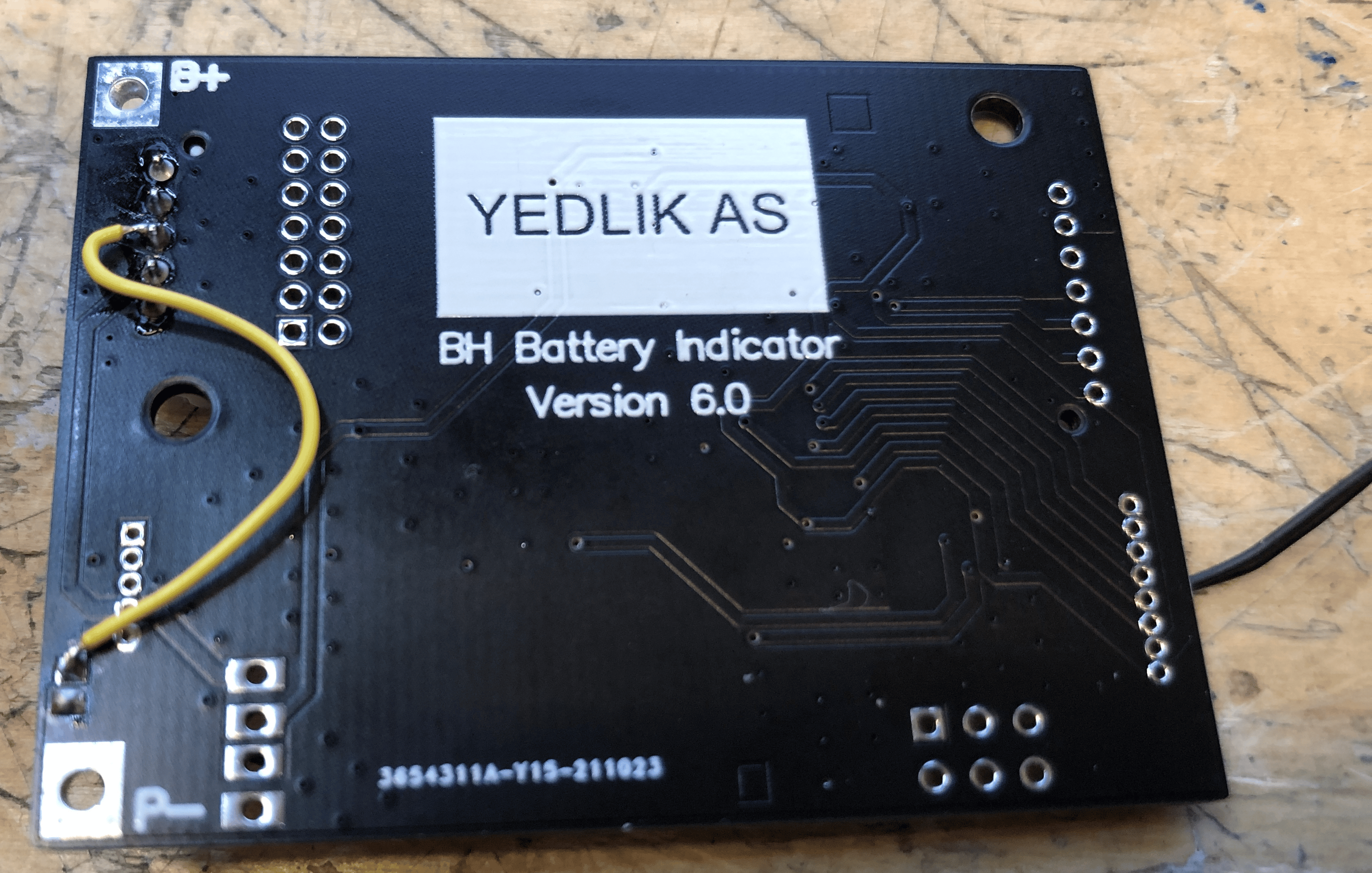
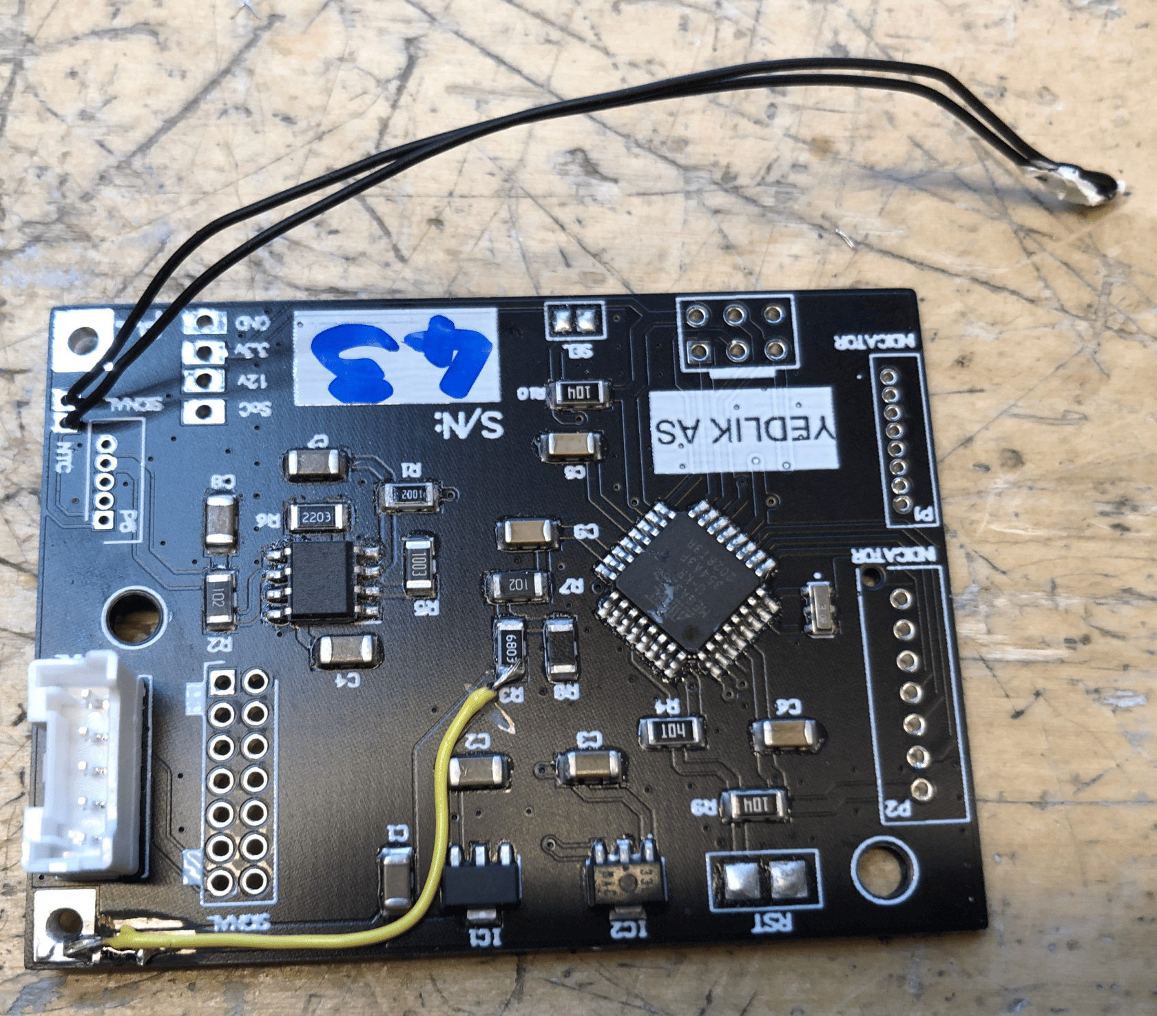
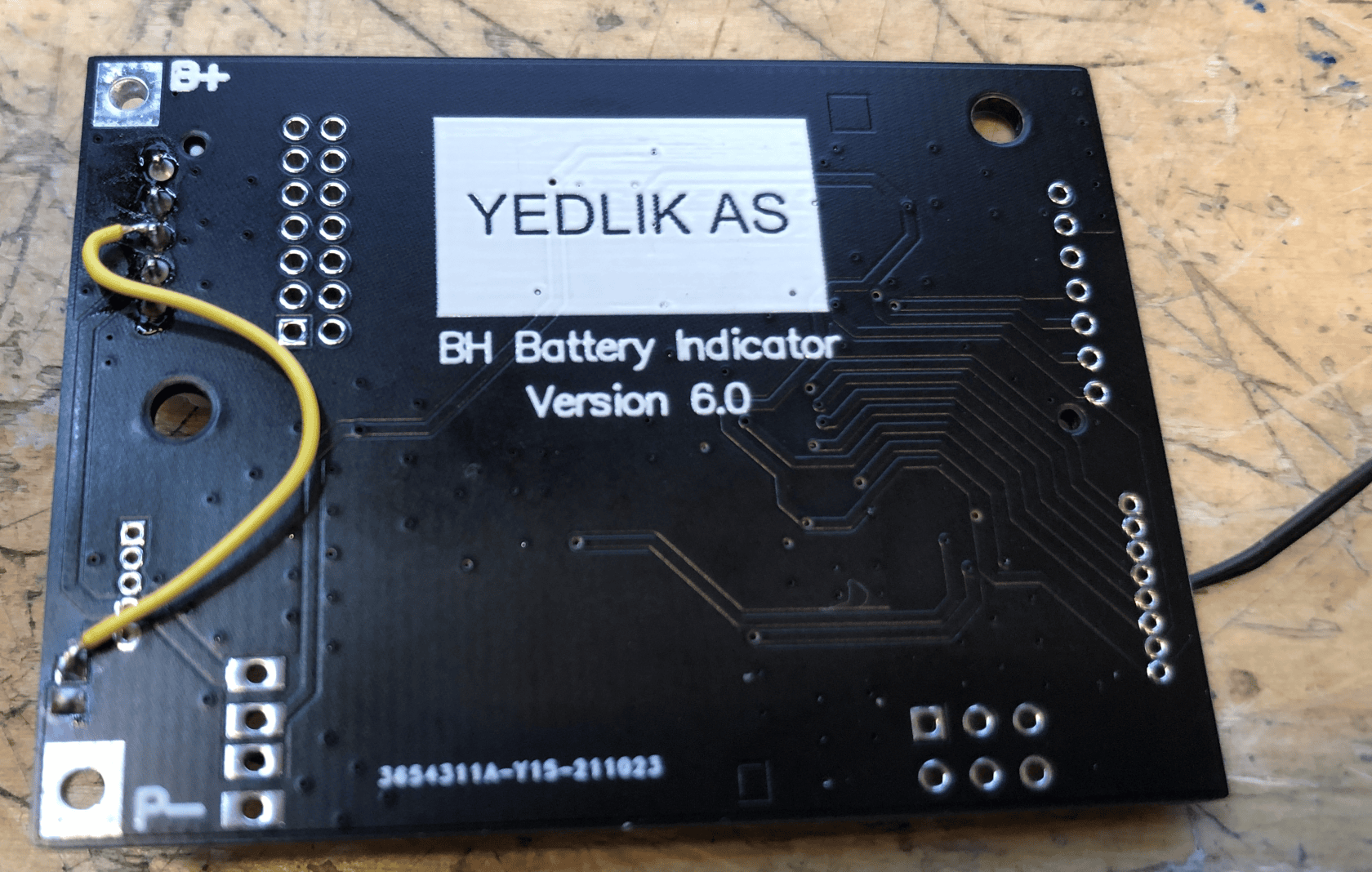
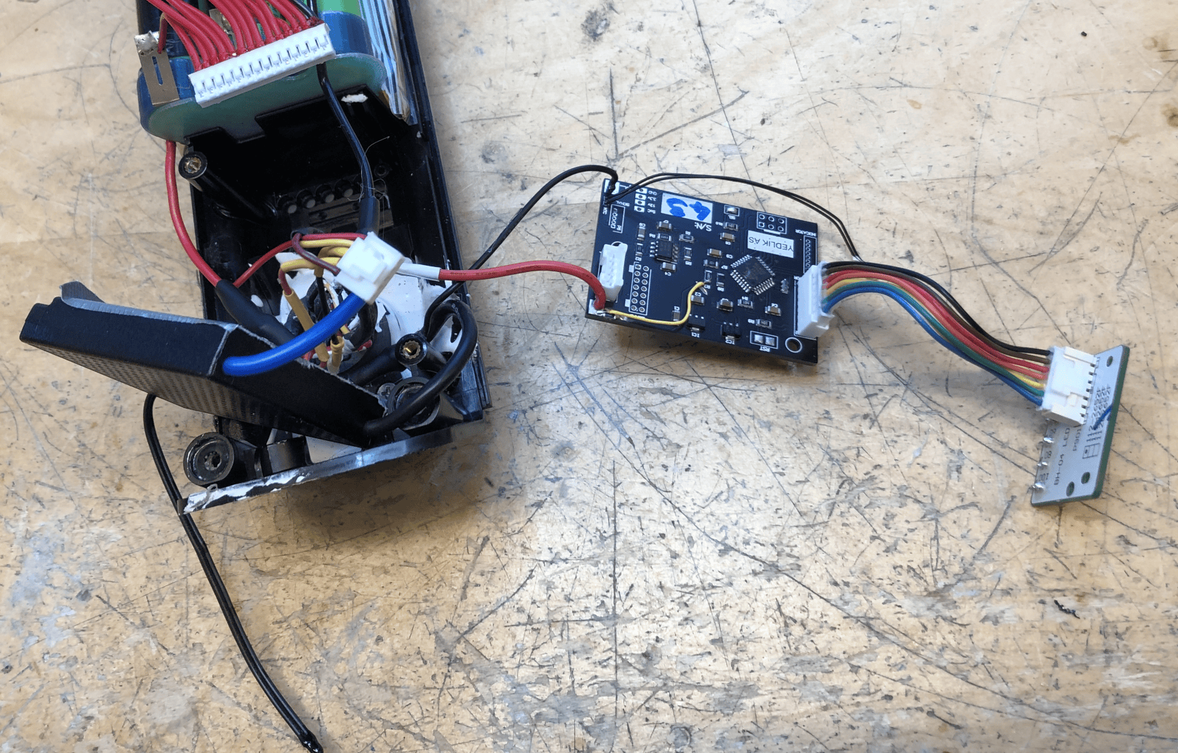
- The LED indicator cable is too short to reach the connector
- The board must be placed upside down!
Further observations
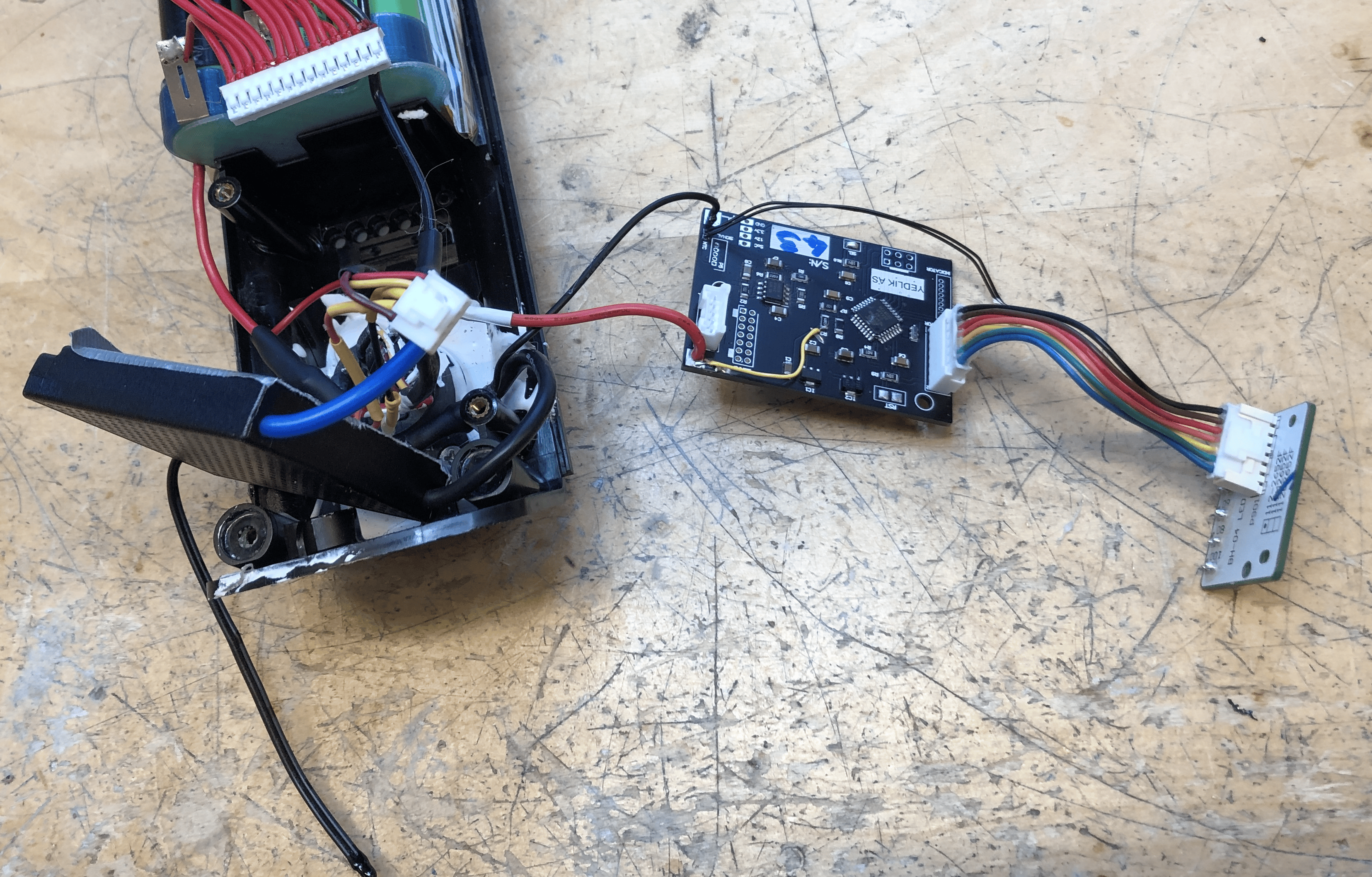
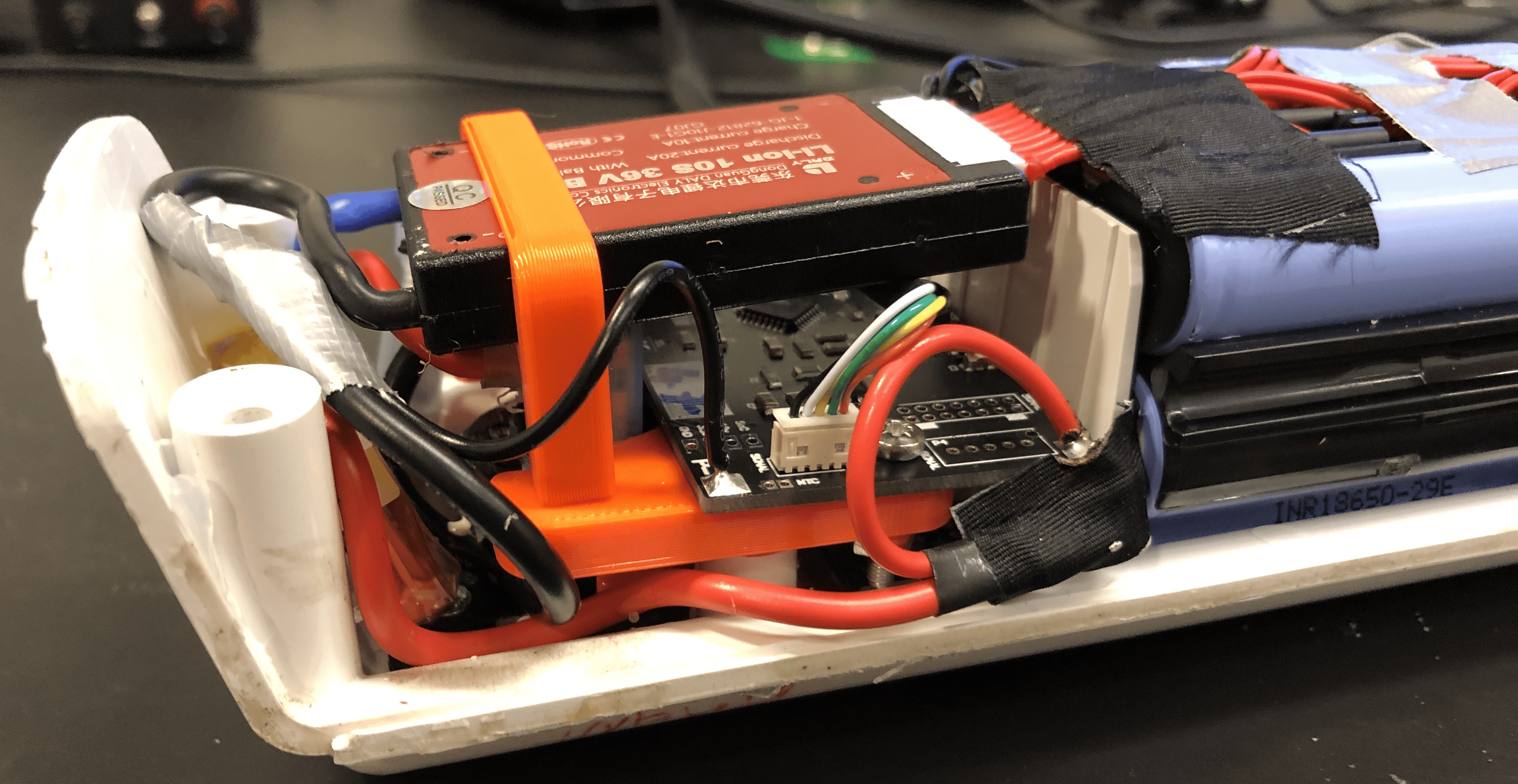
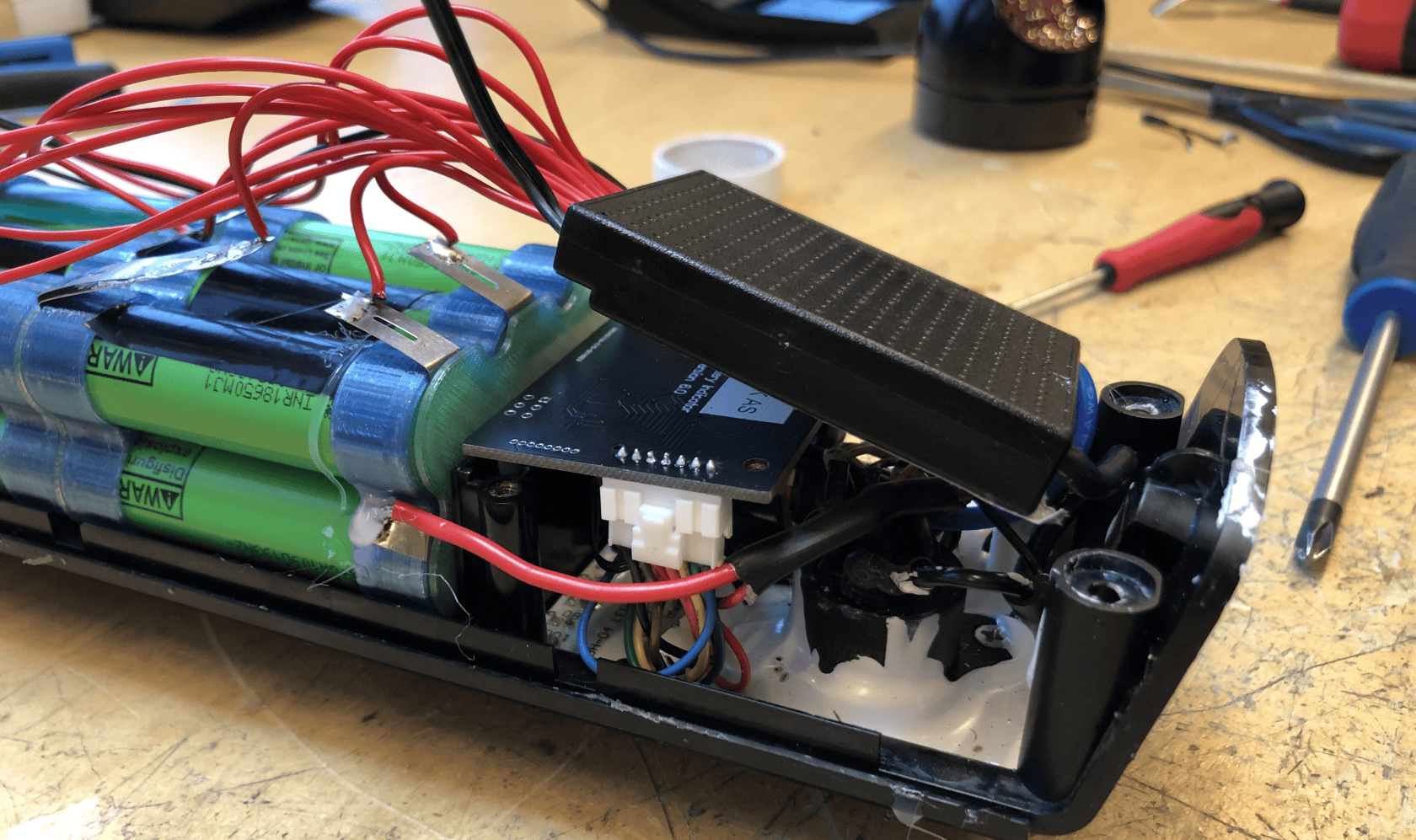
- There is very little space. The idea of a plastic holder to keep everything organised may be flawed - there is just no space for it?
- Especially with the 48V large BMS.
- It would be very helpful to find a method to get 'just long enough' sense wire harness.
- I could make the board at least 5 mm narrower - it would further help with wires!
- The RST pins should be smaller, like the selector
- The power should be from a connector too! Less clumsy that way, less chance of breaking the board
- Shrouded connector, 1.25 to 2.5 mm pitch, 2 poles - like TE HPI or JST ZH or ZX or PH
- OR I shall have two terminals for both - so you don't need to 'split' the wires and mess with heatshrink
- But then I need a bit more space
- One mounting screw hole is more than enough
- Downwards pointing connectors could save further space!
- And make placement less critical - shorter distance for wires
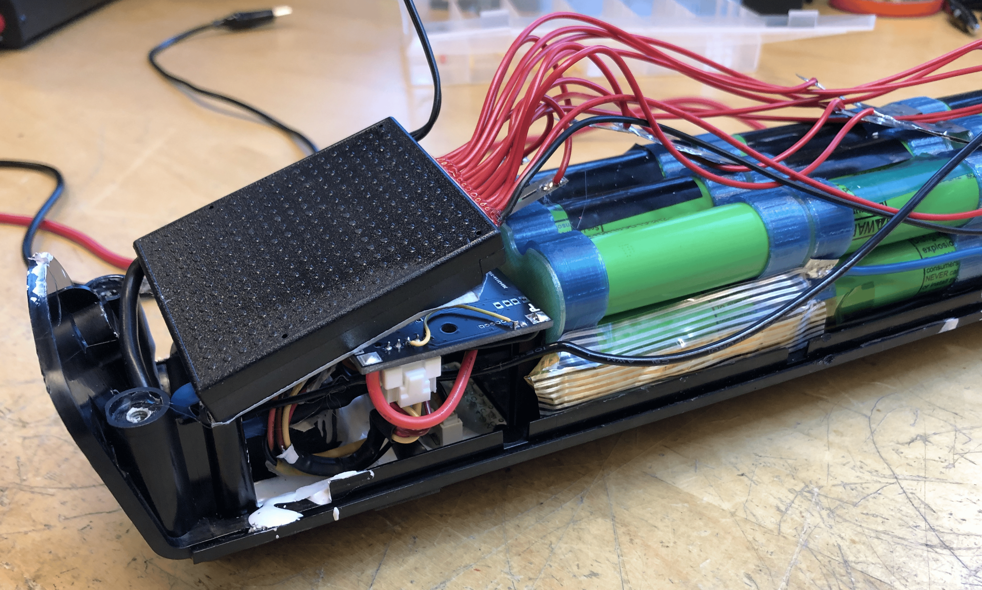
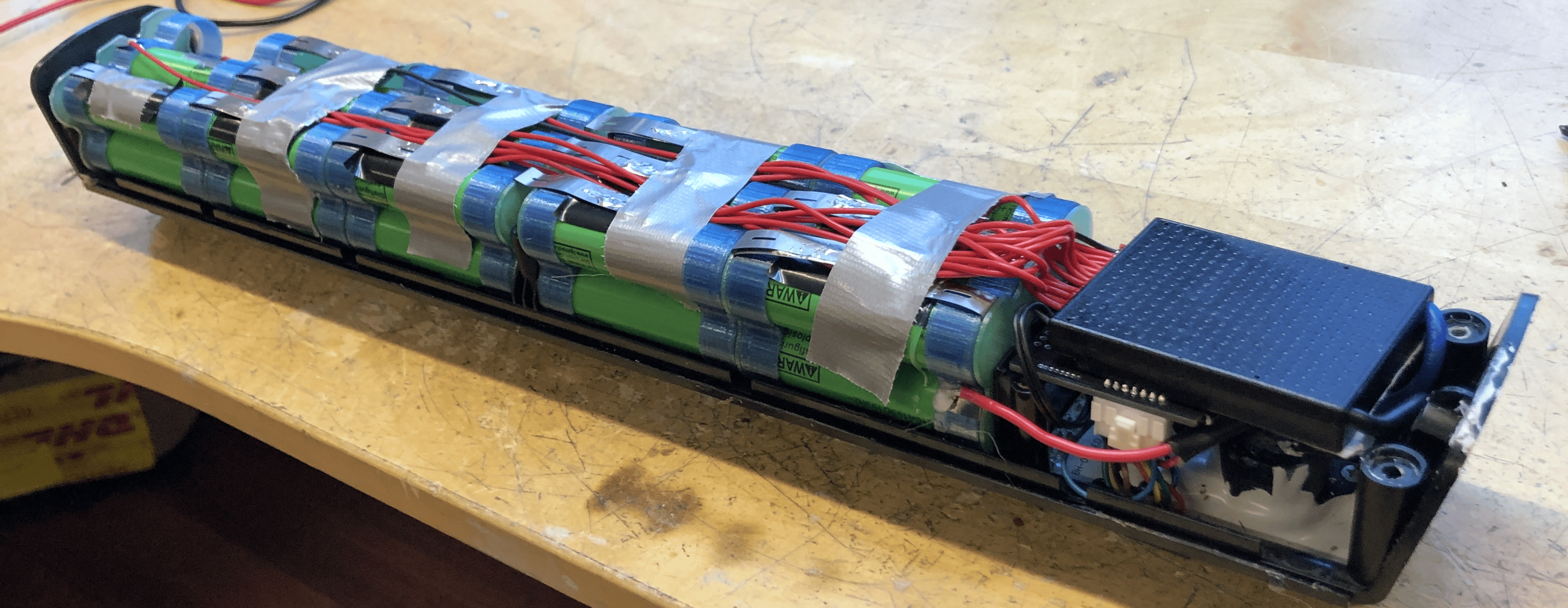
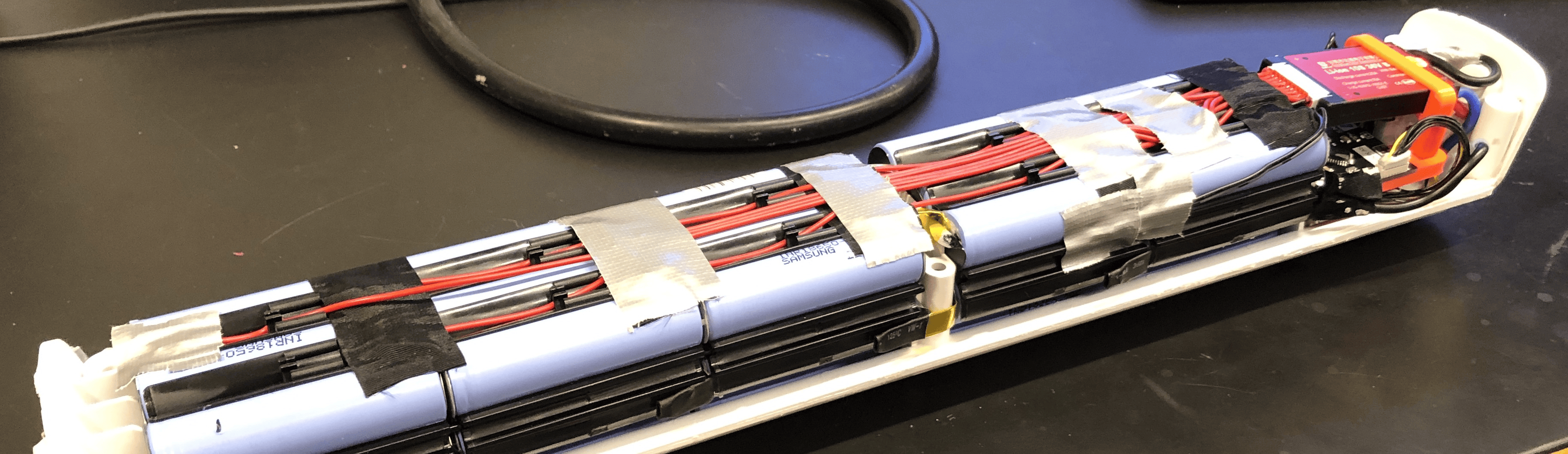
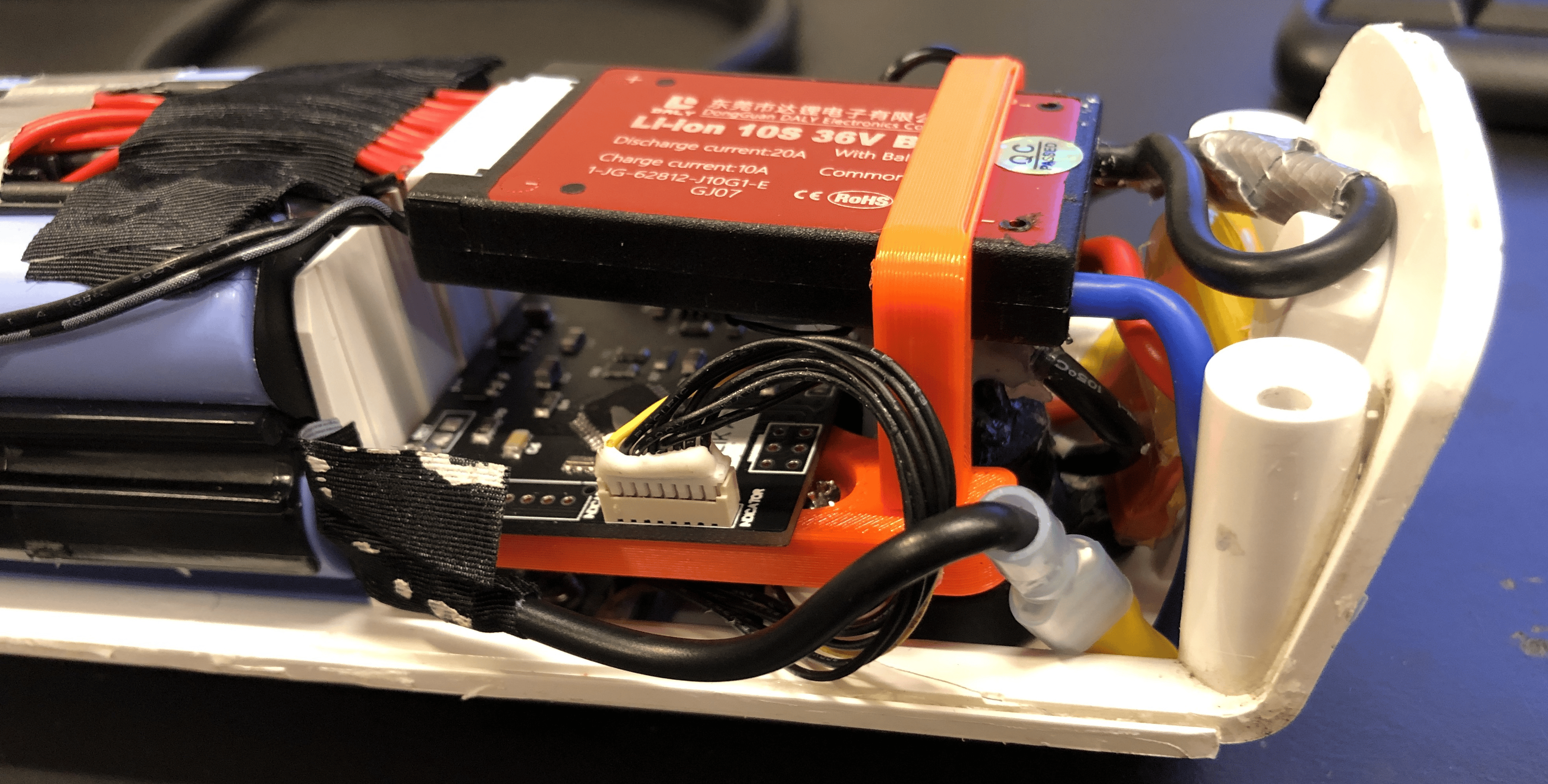
On a 48V white BMS battery


On a 36V green L-shaped BMS battery