
Current limiting on the data output
On the original board, it is possible to pull the data output to 42V, and the current will be only milliamps. In fact, the whole signal will go up - the signal amplitude is max 3.3V or 5V or whatever.
We don't do this. That could be the reason why we killed that motor controller for a customer?
Reverse engineered output stage
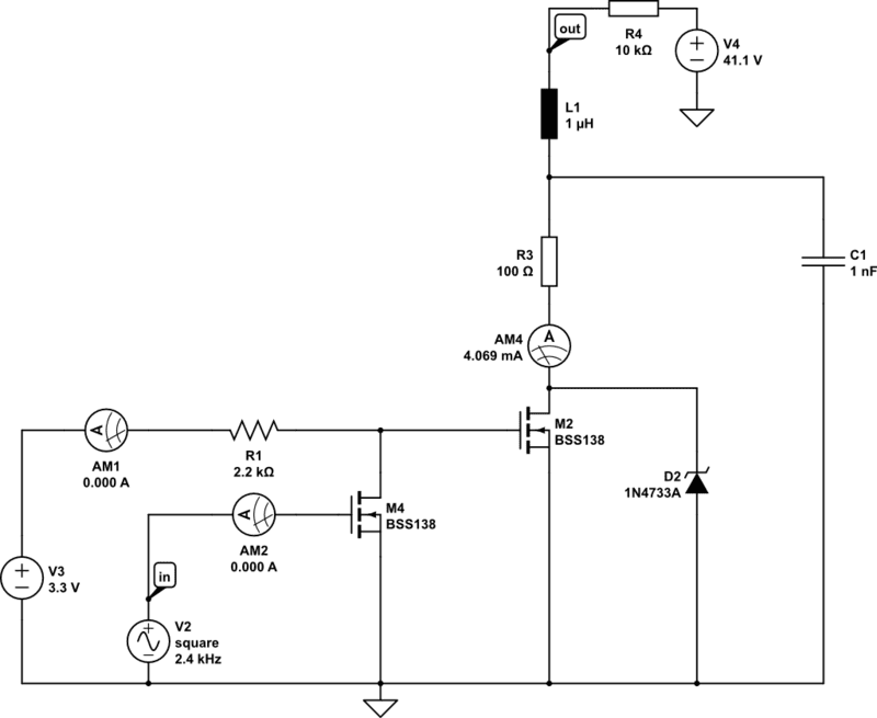
- The value of the inductor in uncertain. Resistance is 0.5 Ohm
- R3 is 100 Ohm for sure
- C1 is 1nF for sure
- Zener diode clamps at 5.1V
- The transistors are unknown type
Simulation vs real deal
Trying w/ 10k:
- 0.4 to 5.4V in simulation
- 2 to 7.1 on scope when loose
- 3.7 to 8.9 on scope when pressed
Trying w/ 4.7k:
- 0.8 to 5.8V square in simulation
- 4.3 to 9.4 on scope
- The resistor gets hot!
Trying w 47k:
- 0.1 to 5.1V in simulation
- 0.32 to 5.68V on scope
47k does not turn on the battery for discharge. 4.7k and 10k yes!
What causes the 'floating'?
If I measure at the top end of the zener diode, I get a square waveform that goes down to zero. But at the output is does not! And my simulation does not explain the extent of the phenomenon. W/ R3 = 850 Ohm, I get a very similar response. But where is the extra 750 Ohm?