
Battery enabler
We need to build a simplified version of this:
https://www.seeedstudio.com/CANBed-FD-Arduino-CAN-FD-Development-Kit-p-4724.html
We need
- Voltage regulator that supports up to 42V
- 120 Ohm termination
Battery enabler hack
The goal is to hack the battery BMS through a CAN communication so it shows the battery voltage at the output terminals.
We found out that we can do that if the battery constantly receives the 0x09A identifier (each 100 ms). Then, the hardware needed is:
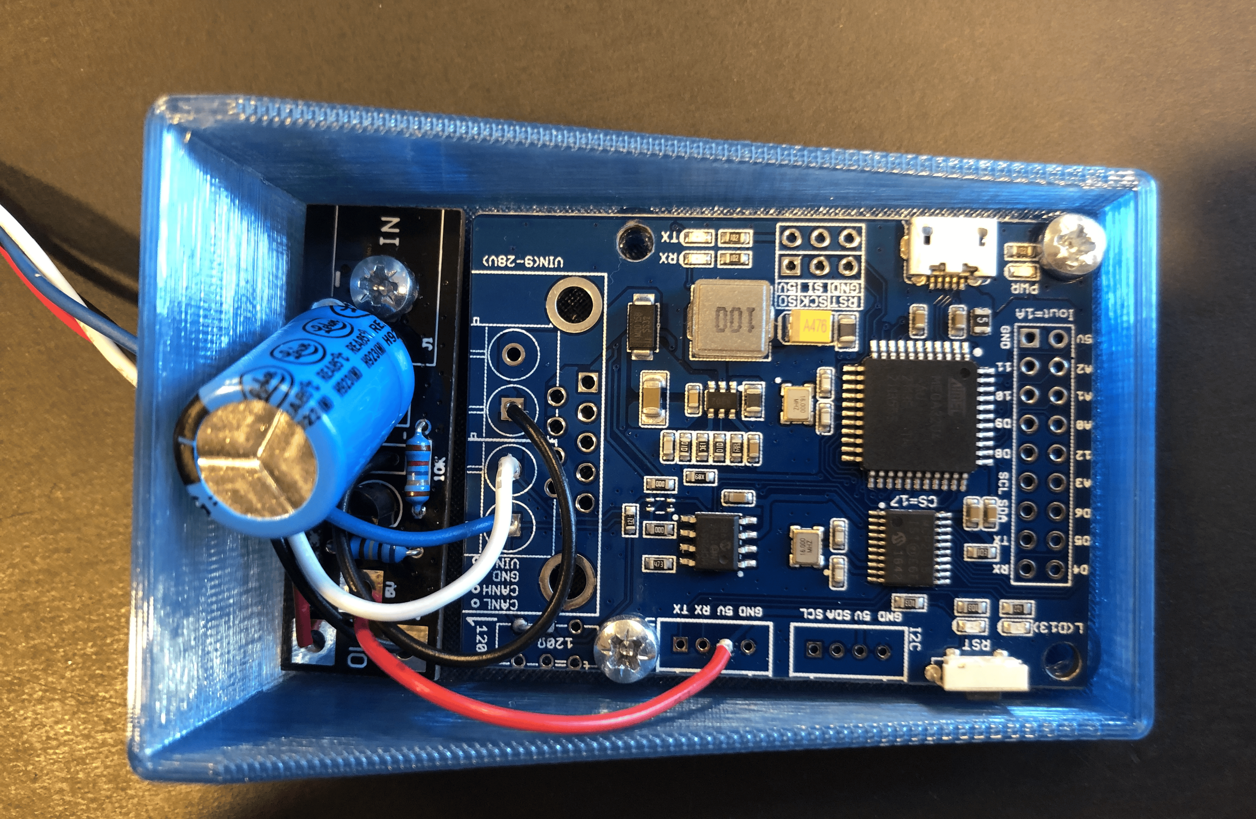
- CANBed Arduino board (includes the CAN module for Arduino)
- Suitable 5 V power supply
The power supply
A LDO is the most affordable option for this. It has been selected attending at 2 main concerns:
- Current consumption. After realize that the CANBed board consumes around 40 mA (much more than what some conventional LDO's in the workshop can provide), we selected LR12N3-G. It can provide up to 100 mA and be configured for any desired voltage, getting to withstand up to 88 V at the input.
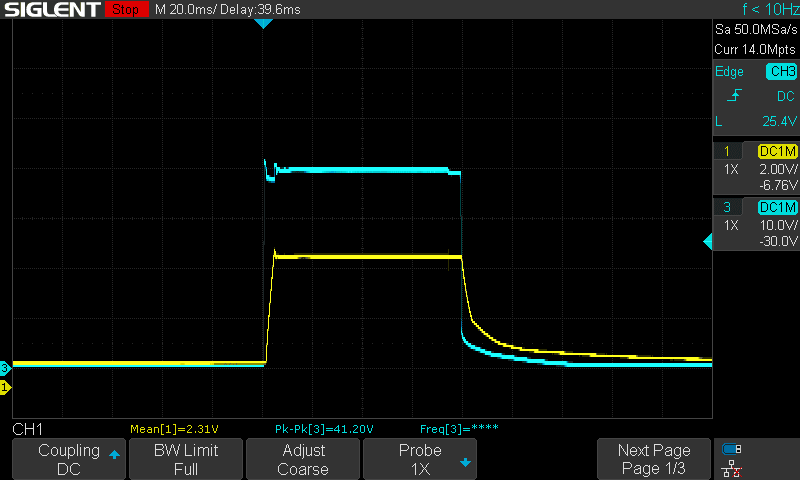
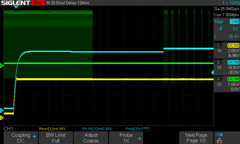
- The delay between B+ and the CAN message. The main issue here was about the start-up sequence. In the moment the battery button is pressed, a B+ pulse arises that should be enough for the CANBed board to power up and start sending the data frames. However, an specific amount of time (around 120 ms) must pass by between. This has been verified with the oscilloscope, notice in picture below how that time is needed between the battery startup and the start of the data frames.
But it was not that simple since the battery pulse only stood for around 20 ms, so, somehow we need to keep that voltage for a bit longer. (In blue B+, in yellow 5 V regulator output )
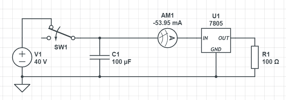
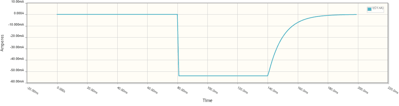
For this we used big capacitors. They are able to store the energy for a shot time, enough for the voltage not to shut down that quick and so the board powers up and has enough time for setting up and start sending the data. The circuit was simulated in CircuitLab, concluding that a 100uF would be the solution.
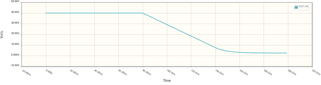
Battery voltage with the cap. Notice how much time it lasts now until we begin to send the data at t = 140 ms
In order for the system to work also when the battery is at a lower state of charge and thereby lower voltage, the capacitor should be sized even bigger. 250 uF is enough even at 25V. The capacitor must be rated for at least 50V.
Once this happen, the B+ appears always on the battery terminals and the board keeps feeding from it. That's how we bring the battery to life.
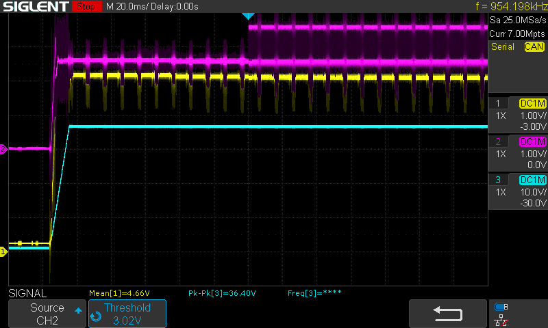
(Blue B+, Yellow 5 V regulator output , green CAN messages). Notice how after around 100-110 ms, the battery is enabled.
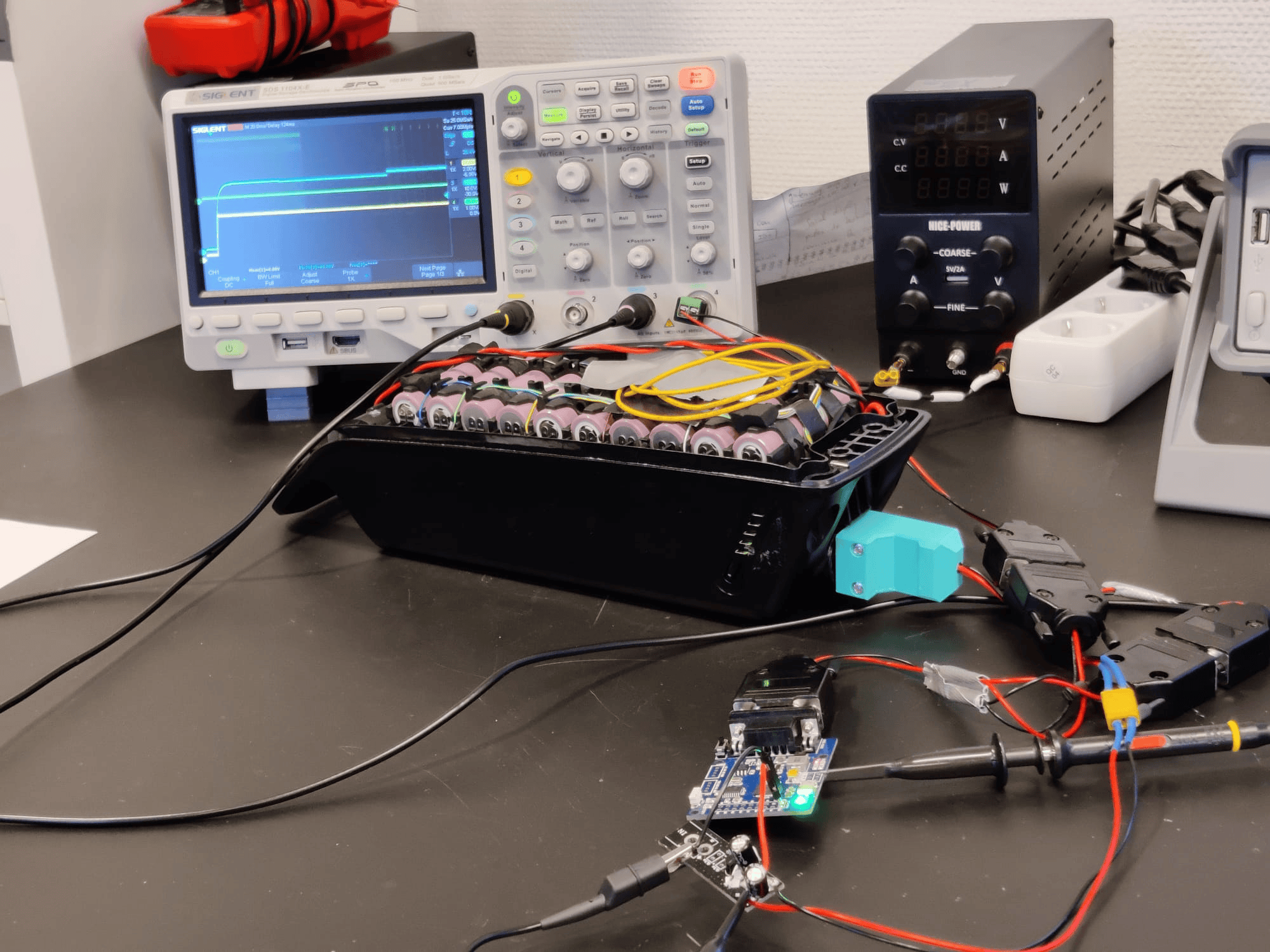
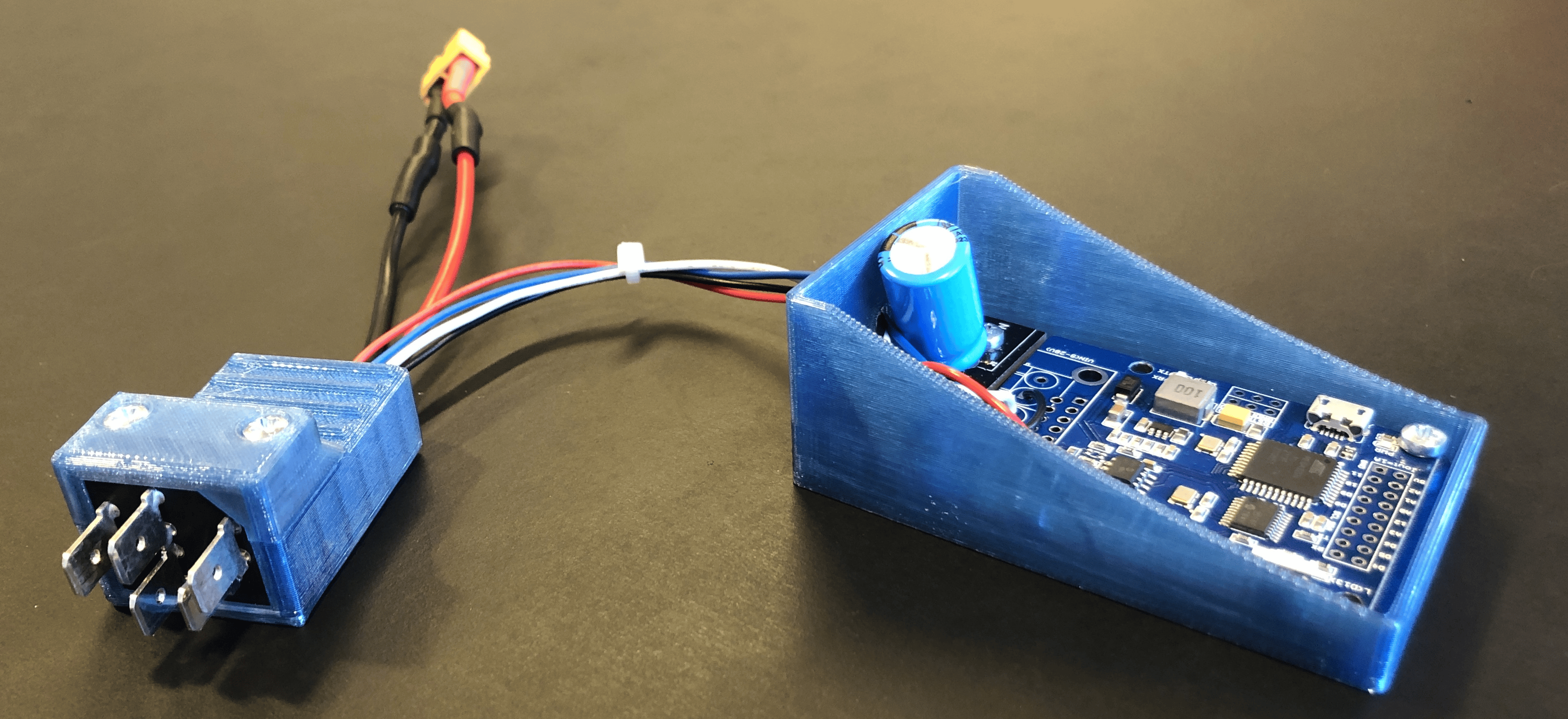
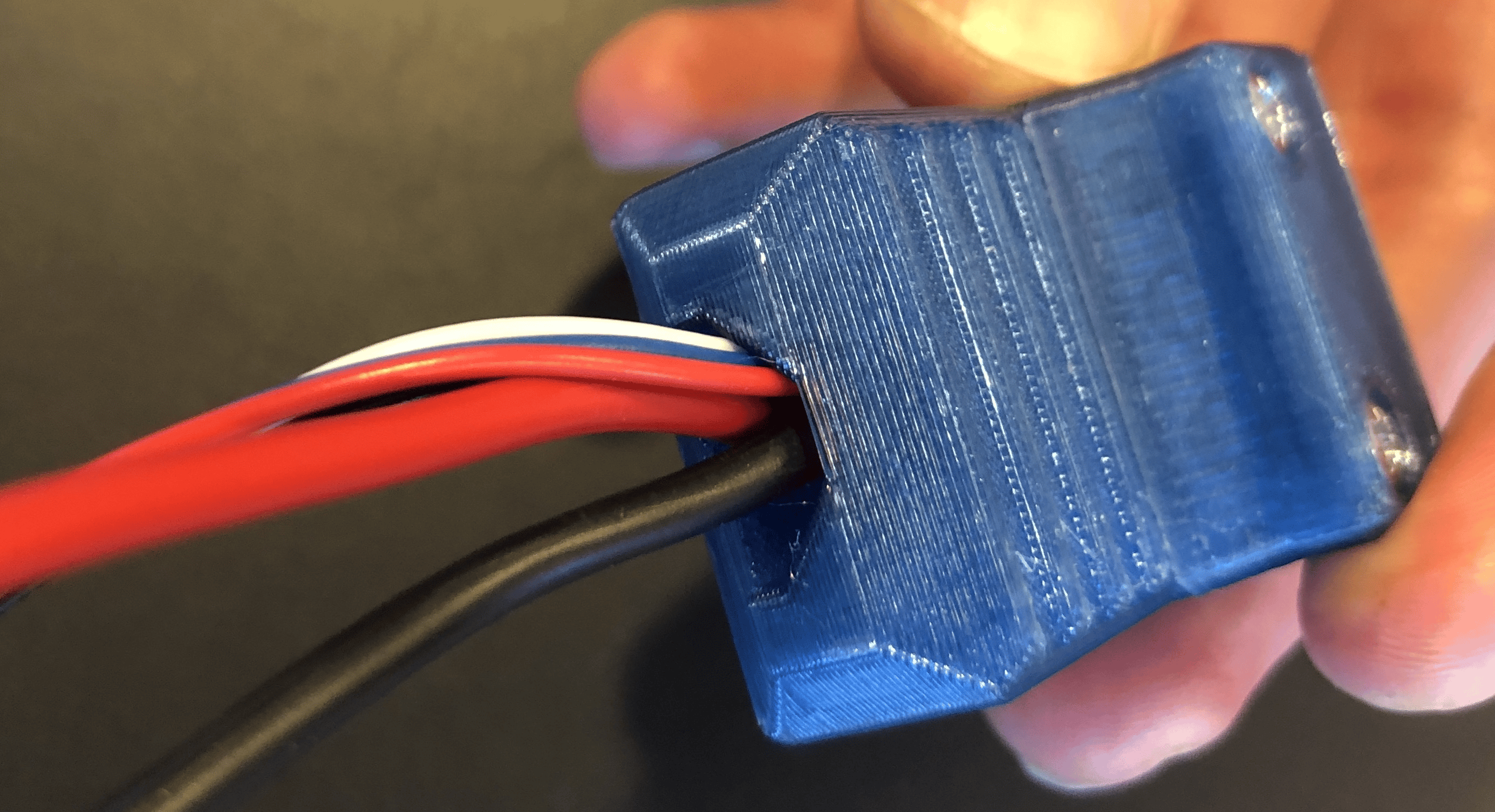
The setup
The code
// send a frame from can bus

#include <SPI.h>
#include "mcp_can.h"

#include <mcp_can.h>
#include <SPI.h>

const int SPI_CS_PIN = 17;              // CANBed CS pin selection
unsigned char data[1] = {0};            // Data to transmit, invariant

MCP_CAN CAN(SPI_CS_PIN);                // Set CS pin


void setup()
{
  CAN.begin(CAN_500KBPS);
  CAN.sendMsgBuf(0x9A, 0, 1, data);   // send data:  ID, frame type, DCL, data

  for (int i = 0; i < 1000; i++)
    delayMicroseconds(100);           // send data every 100ms
}

void loop()
{
  CAN.sendMsgBuf(0x9A, 0, 1, data);   // send data:  ID, frame type, DCL, data

  for (int i = 0; i < 1000; i++)
    delayMicroseconds(100);           // send data every 100ms
}
Final version

No comments to display
No comments to display