
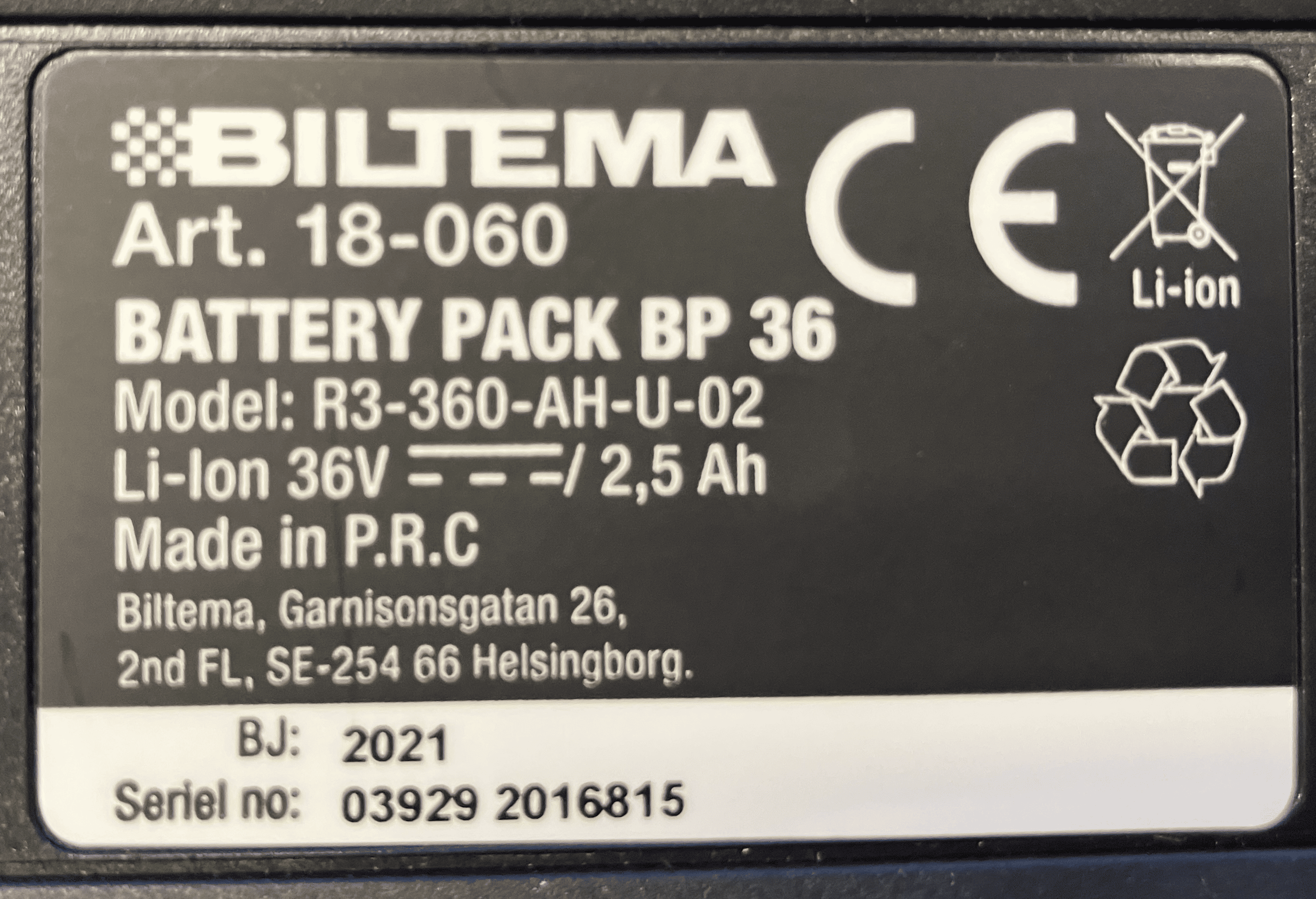
Biltema MultiX 36V
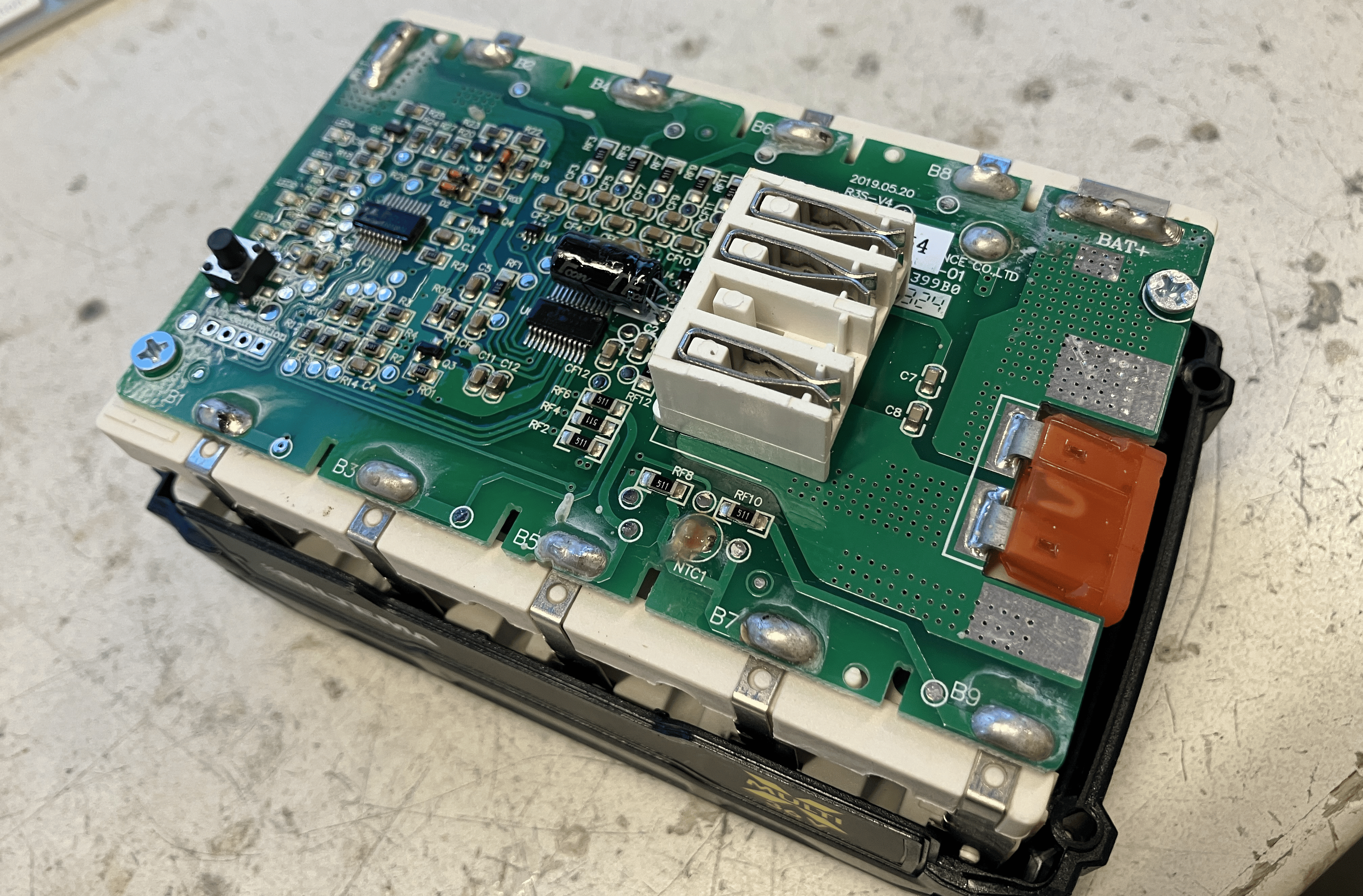
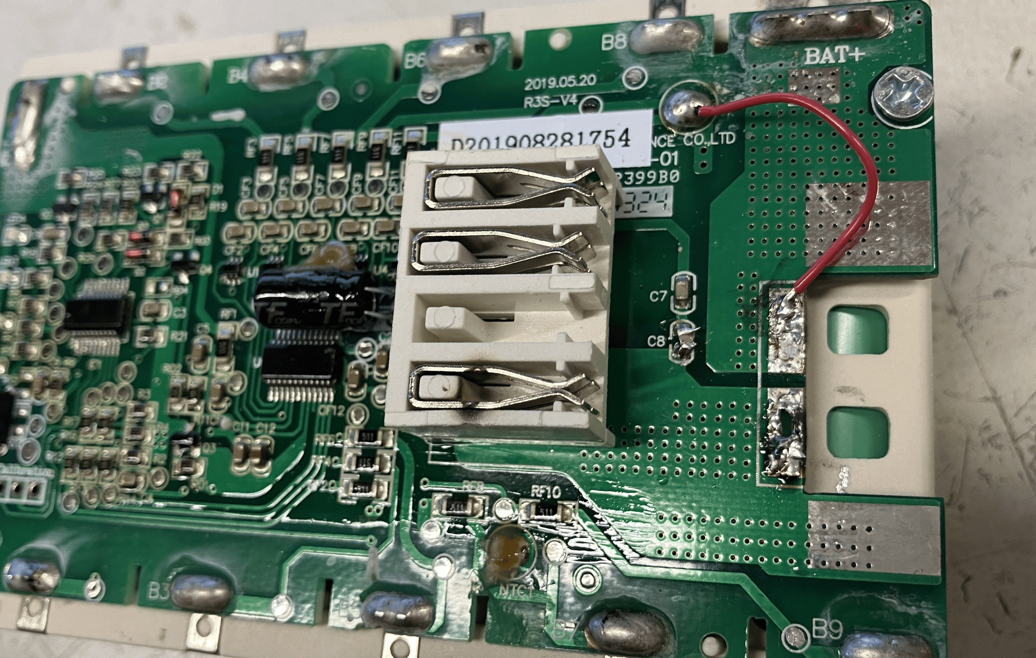
10S1P arrangement, Samsung 25R cells. (High power, low capacity!) The BMS does not actually have a switch, it just enables / disables the charger / device via communication. The BMS has a 40A car fuse soldered into the board.

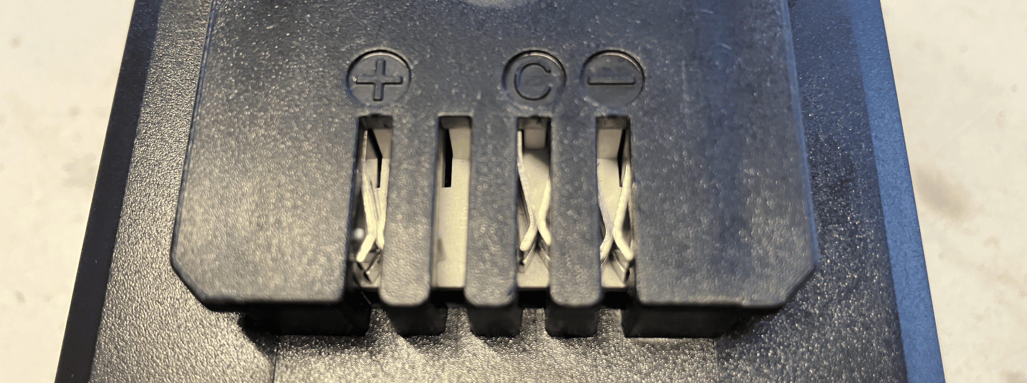
3 pins:
- P+
- COM
- P-
Communication
As seen from P- to COM:
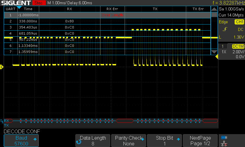
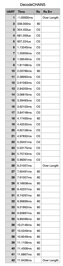
It is a kind of an UART, I get legible stuff out of it at 57600 8N1. Because of the super repetitive pattern, I am a bit worried if I might be oversampling it, and indeed it is a lower baud rate with a different parity/stop bit situation.
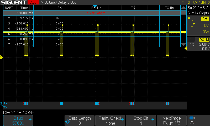
Weirdly, amplitude of the second block is higher: 5V, while the first is only 4V. This leads me to believe that the first part is sent by the device, and the second part is the answer from the battery. It is higher amplitude because I had the probes sitting on the battery. This handshake happens every 135 or so ms.
It is strange that there is half-duplex communication happening. I've never encountered that before, would need to learn more to interface with this.
The battery allows itself to be discharged without any communication, since it has no FETs or relay to stop it. Therefore it makes sense that it is the device that sends first, and the battery answers. It also explains the behaviour of the device when powered without communication: it would work for a few seconds and then shut off. It does it because it thinks it is protecting the battery.
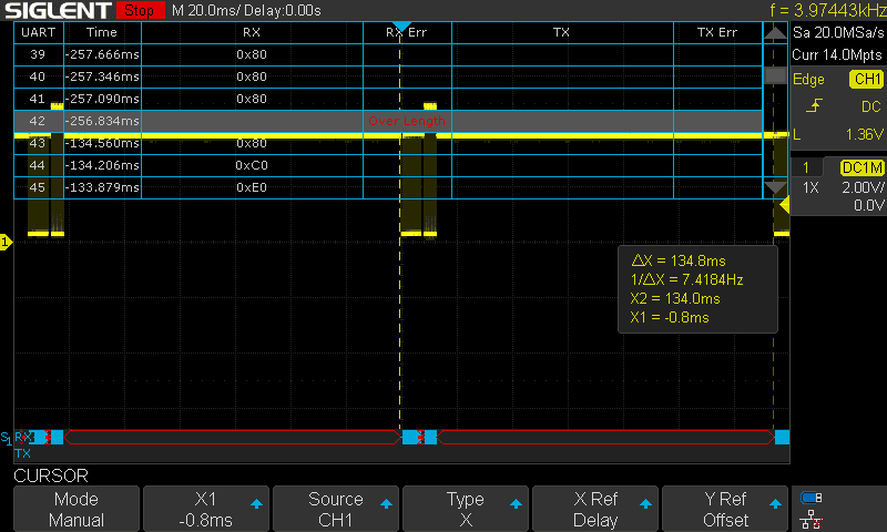
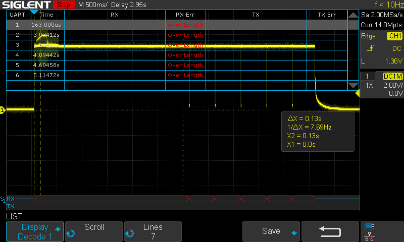
Startup
It is the chainsaw that pulls up to 5V, and it pulls to zero to initiate communication every 500 ms five times, then it gives up. The chainsaw works for that few seconds.
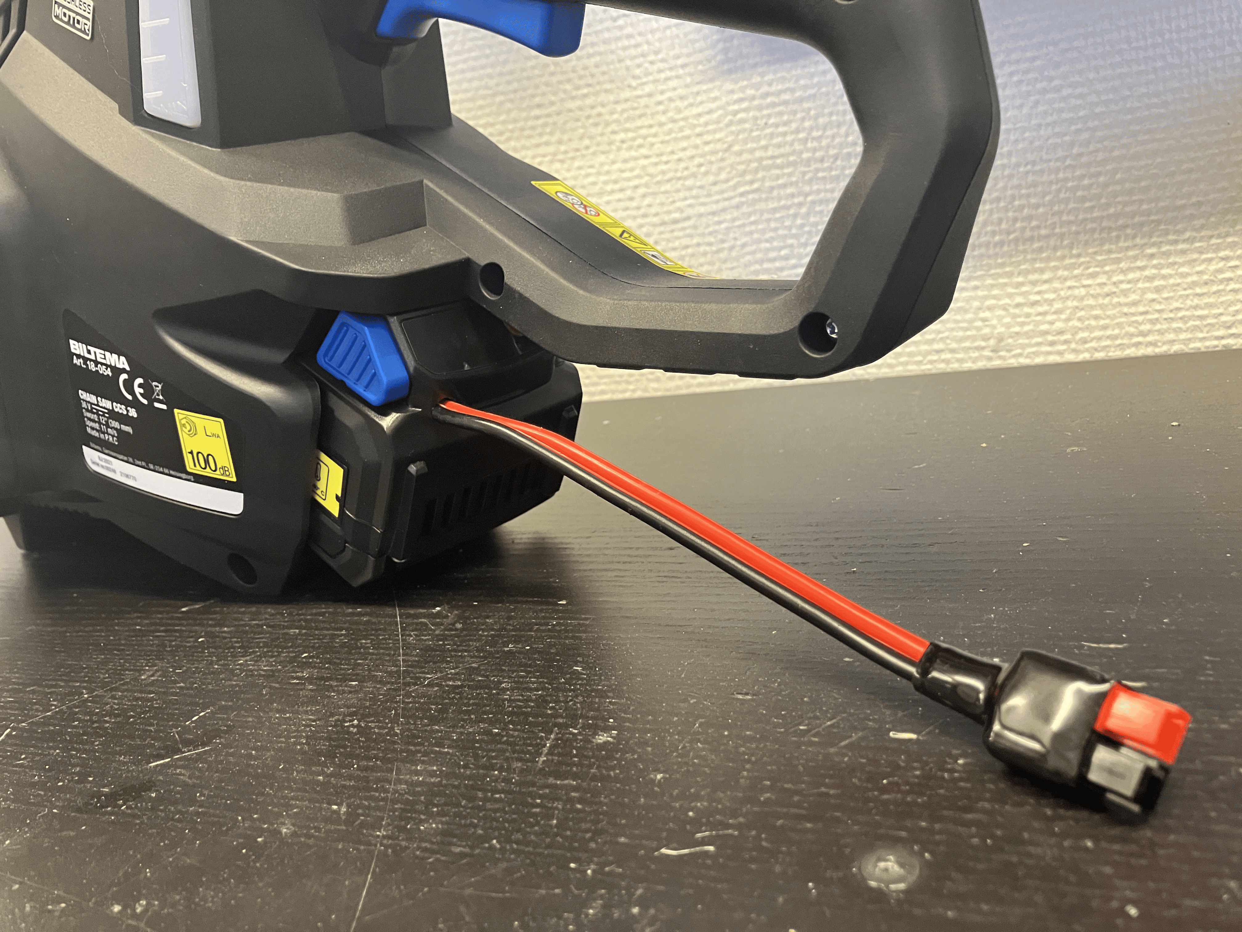
Hacking an external battery solution
Original idea w/ maintaining the original battery
- Disconnect the 40A fuse from B+
- Attach the wire to P+
- Attach the wire to P-
- The original battery will do the communication
- The power will come from the new one.
- You need the charge the 'communication battery' every second months...
Problems:
- The fuse disconnect is noticed - it is using the other side of the fuse too
- I would need to desolder the pin itself - but then there is no mechanical support anymore
- Plus it is super hard to desolder due to lack of space
- Ditto for cutting it off
- Solution: a super smart bypass!!
- But it was not enough, I also would have had to cut the trace just next to it.
- The biggest problem:
- How is he going to charge up this battery now?
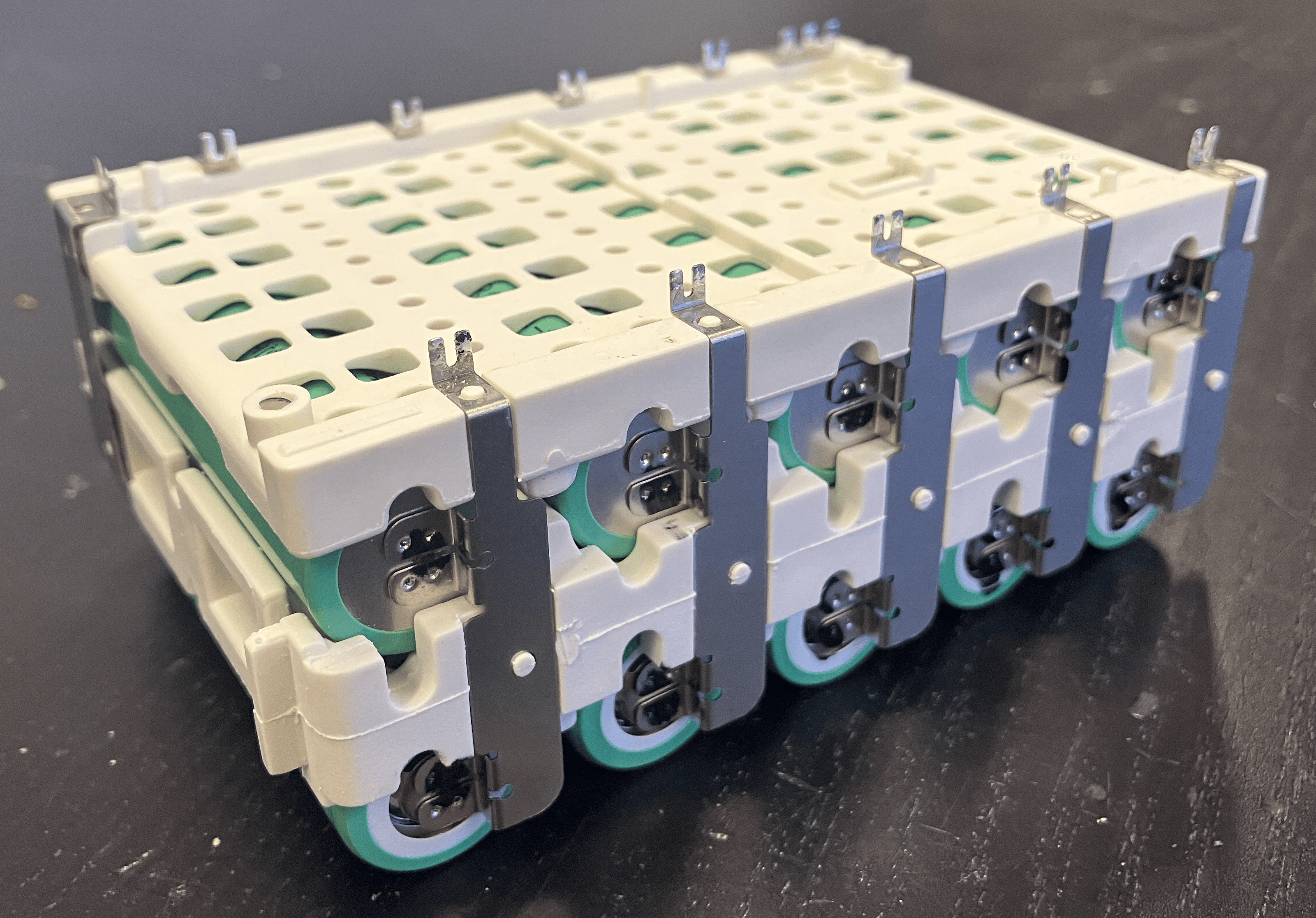
Final idea: replacing the cells with a plastic frame and resistors
To make the BMS believe that the cells are there, I used a 200 Ohm resistor to replace each, and connected the terminals of the remote battery to B+ and B-.
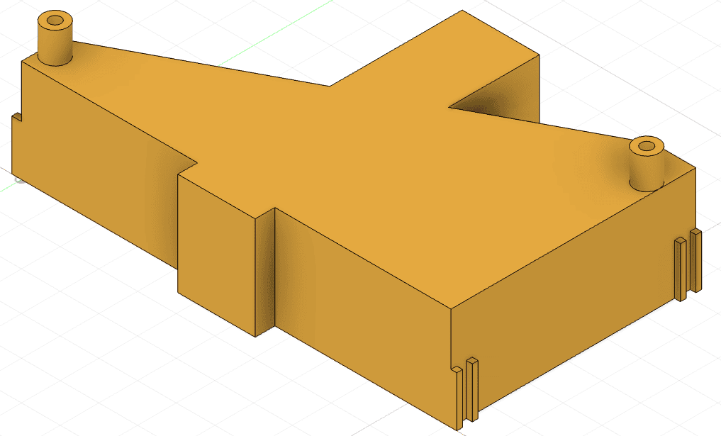
To keep the connector and the button in the right place, I 3D printed a holder to screw the BMS to.
Improvements
- The 3D model is still a bit flimsy and hard to put together. That would need to be done bettery.
- No need to remove the fuse.
- No need for that bypass wire either
- No need to mess with the caps..
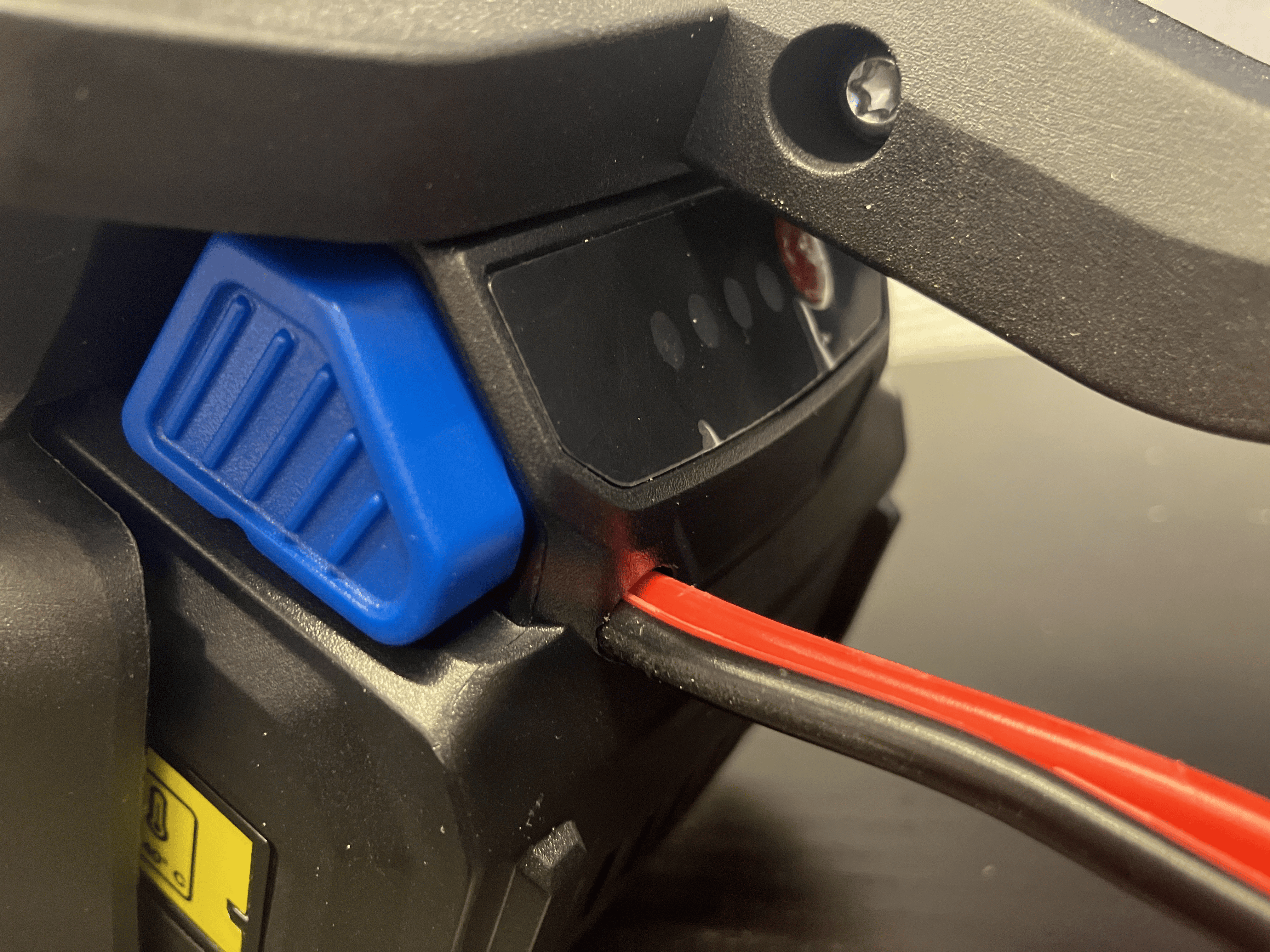
- The wire should come out from the bottom plastic, not the top..
- The resistors should be on a PCB, it would allow much cleaning wiring and would be more robust.
- The hole needs to be sealed obviously.
Of course the holy grail improvement would be to buy a similar plug, 3D print the entire box with locking mechanism, and have an Arduino sitting in there with a power supply doing the communication. That is a big project.
No comments to display
No comments to display