
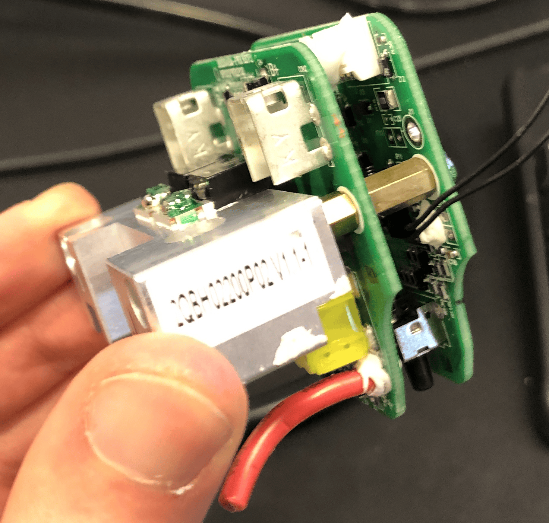
Flat 36V batteries with green 'sandwich' BMS
These BMSs have the LEDs and the button built in, not on a separate board - making our life more difficult.
The white BMS's LED board could fit into these - but unfortunately there are no screw holes. Glueing is not a good idea, because:
- If you mess up, there is no going back
- It seems that the superglue messes with the button itself?
To solve this, I developed 3D printed holders - to be tested.
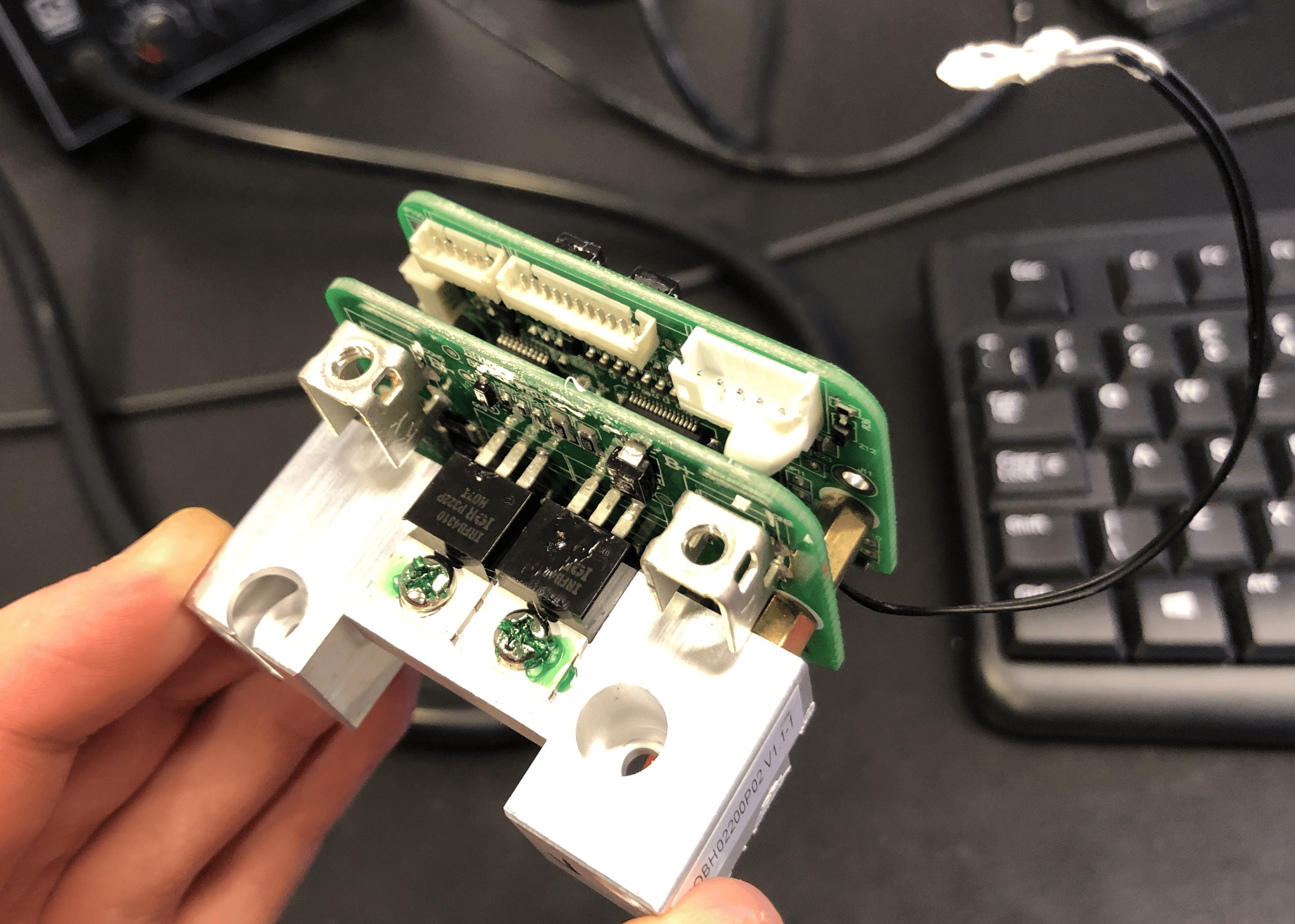
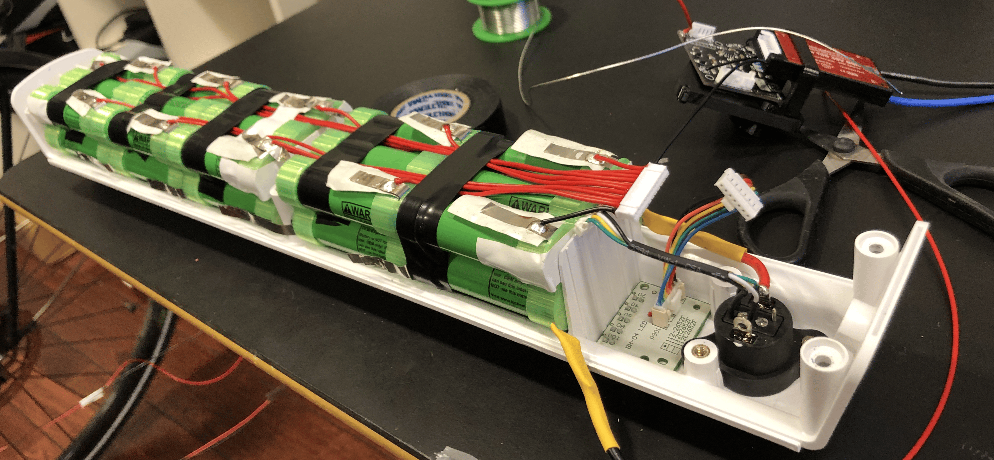
The two screws that hold the BMS to the plastic bottom case are located the same as on the newer L-shaped green BMS - therefore the same 3D printed BMS-holder can be attached. Note that the tall crimp terminals don't allow the BMS to go in place - they need to be removed, the the power wires soldered directly to the connector. SOLDER QUICKLY, because if you melt the connector, you are fucked.
On the picture, the red power wire is too short - it blocks the BMS holder. It should have been one cm longer.
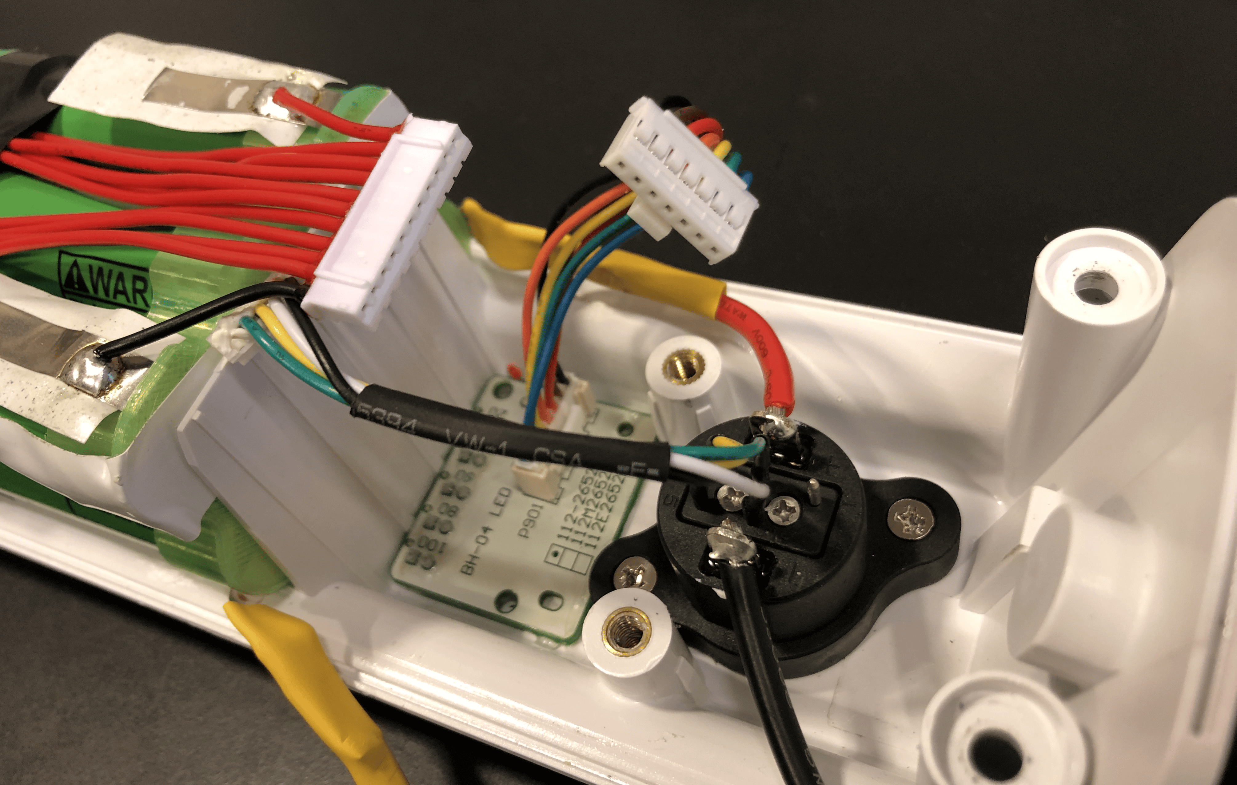
The connector signal wires connect to the BMS with a 5-pin JST, part number B5B-PH-KL (LF)(SN):
https://no.rs-online.com/web/p/pcb-headers/1755461
However, only 4 out of the 5 pins are used. The white one is the SOC signal. That goes to pin 2, exactly the same as on the last generation white BMS boards, where they used a 5-pin JST PA connector instead. If not on stock, this can be acheived by cutting a larger JST PH2.0 connector.

The LED harness needed to be extended to work with our v6 board.
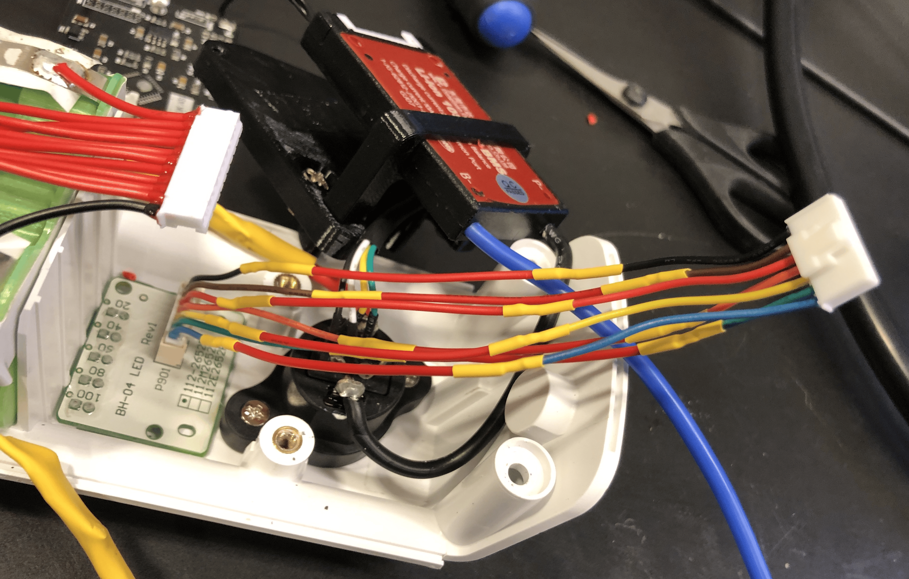
It is important to cut the sense harness just long enough, so that it will fit nicely:
The BMS holder's arc is annoying. It should not be always attached to the bottom part of the holder, only in the final assembly. I need to dream up a way to improve this.
No comments to display
No comments to display