
Troubleshooting: Output oscillations
The SOC output had a lot of noise on it, causing the displayed percentage on the display to move up and down.
First, it was discovered that a capacitor on the active filter was incorrectly selected - 0.1 uF instead of 1 uF. Changing that to 47uF reduced the noise dramatically, but it was still too much.
Two test rides were made, both confirming that the oscillations on the displayed percentage still happen, although rarely. It was also demonstrated that the percentage drops way too quickly - the software’s averaging is way too fast.
Was 47 uF simulated as well? What difference does it make compared to the originally designed 1 uF?
It seems the sizing of the active filter was probably good, but maybe due to the noisy supply of the op-amp, the output is not good enough. Some caps on the op-amp power supply improved the situation, but not enough. Maybe because they were poorly placed THD caps with long leads?
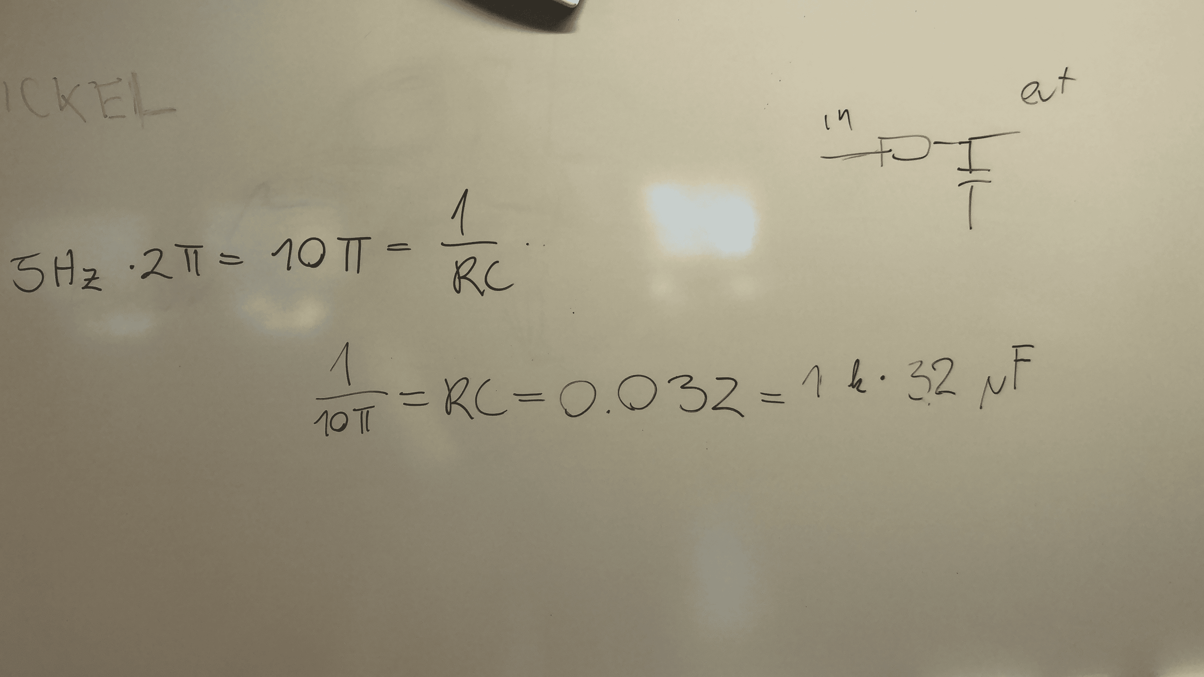
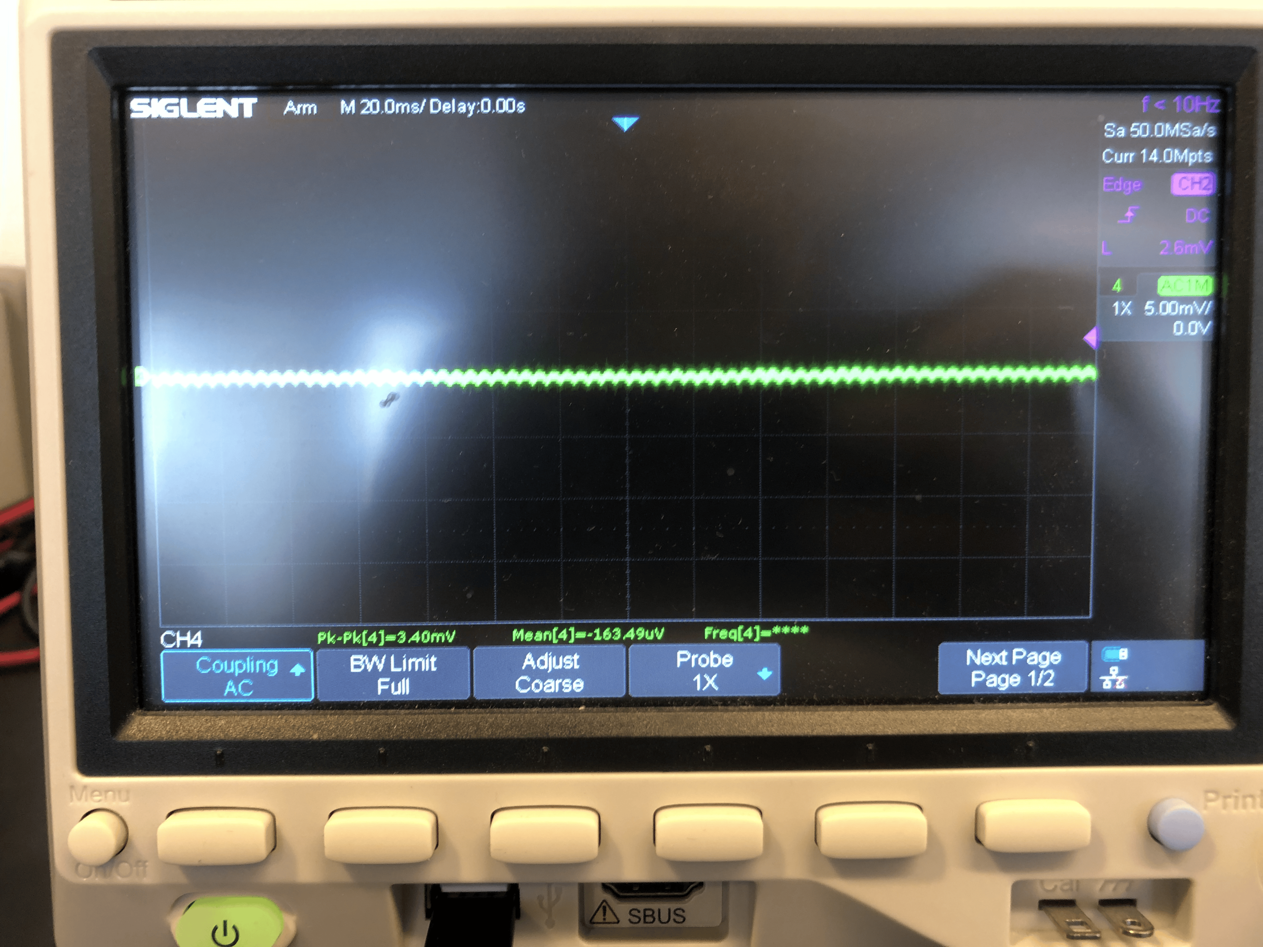
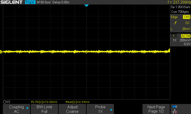
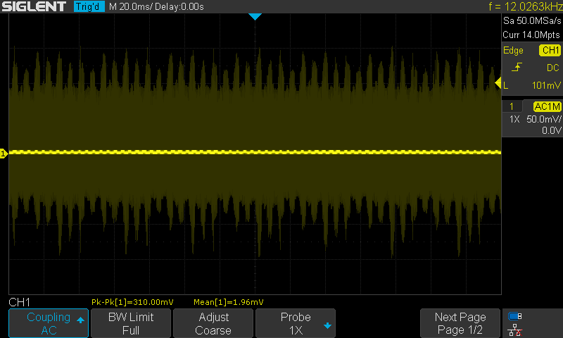
The most dramatic improvement was achieved with a passive filter following the active one. The values R = 1kOhm, C = 33 uF give a cutoff of 5 Hz, and the noise p-p is only 3 mV, good enough for our application:
I cut off the caps from the op-amp power supply, the output was equally clean.
Normally, you would not need a passive filter to follow an active one - the signal should be clean enough. We need to understand why it is not.
Todo
- Talk over the active filter design. Make a prototype. Test for noise.
- Make sure to write an article on filter design
- Outline what mistakes were made, and how they were uncovered and fixed
- Try to figure out why the active filter on its own gives bad results - demonstrate the theory with an experiment!
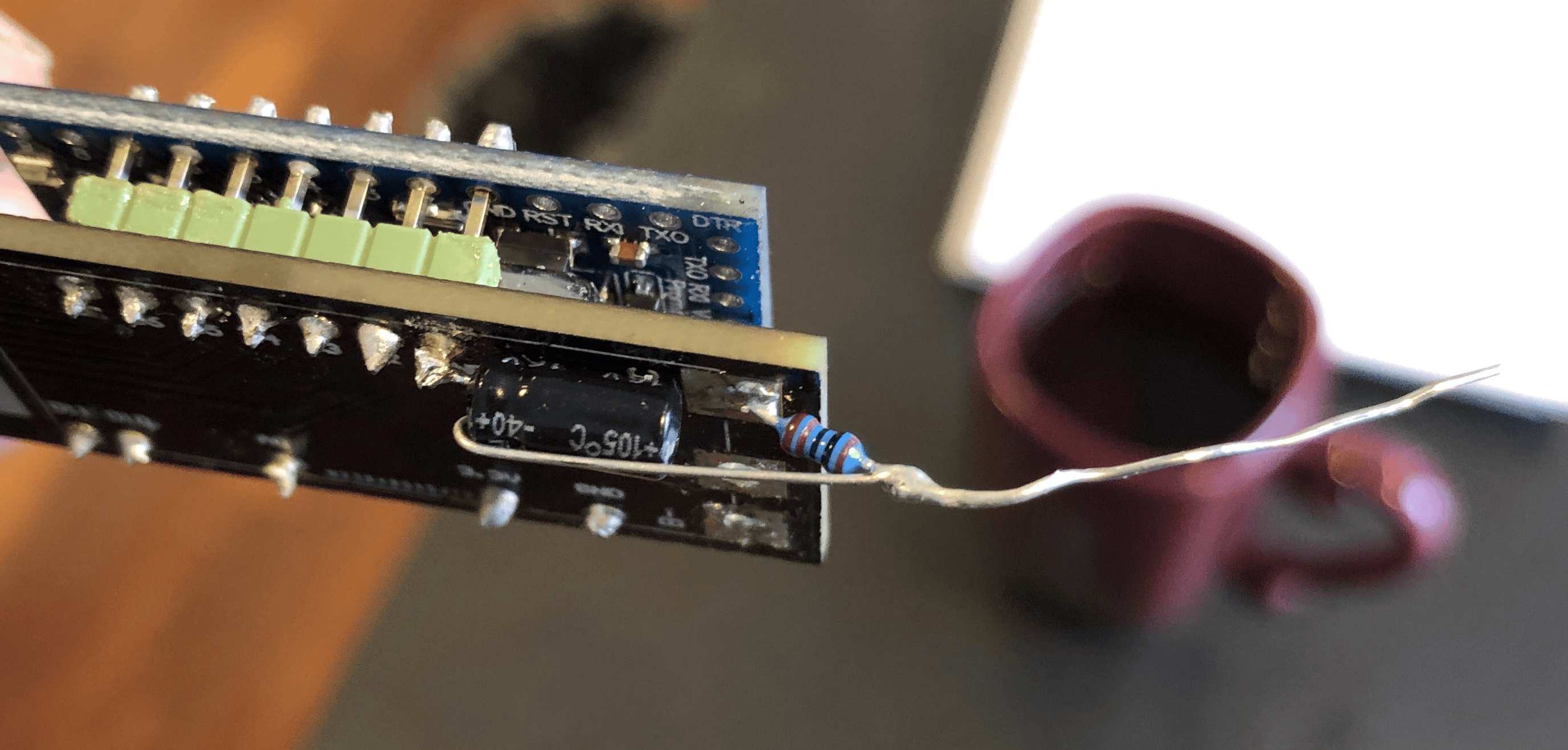
- Smooth installation of passive filter:
- 1k resistor goes on SOC output
- 33 uF cap goes on B-
- The other legs of these guys join together and form the new SOC output
- Must be done safe and durable!!
- The software must be modified
- Lower the number of records to 30
- Average of the 10 highest values of the 30 records
- Sleep five times 8 seconds in a row!!
- The passive filter equipped and software updated board must go into the bicycle
- Bicycle must go for testing, written report needed
- The board design must be updated to incorporate corrected active filter, and maybe passive filter too?
- The updated board design must be sent into production
- The assembled boards that we already ordered must all be reworked after arrival
- Change SMD capacitor
- Add passive filter
Battery voltage dependence
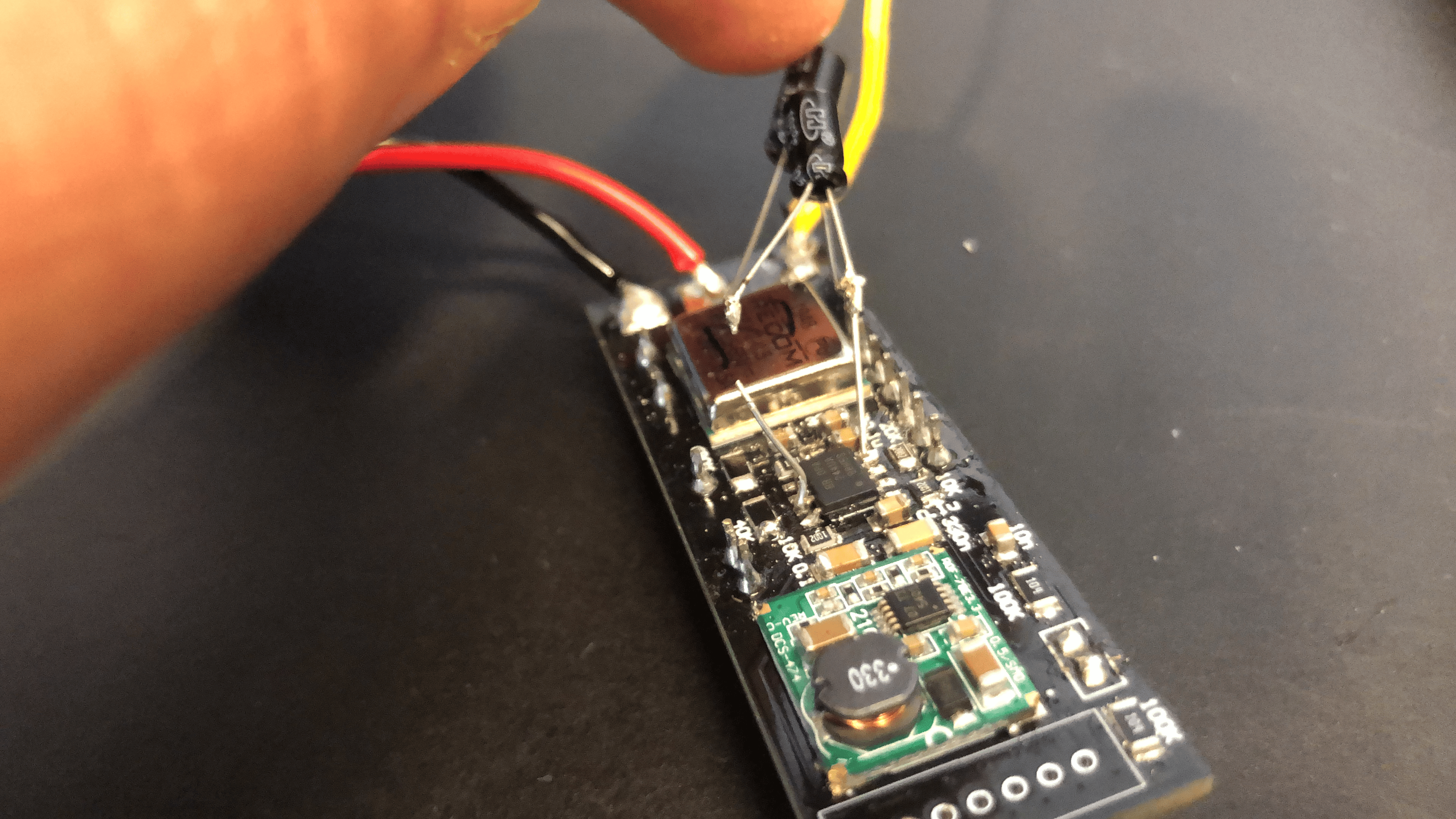
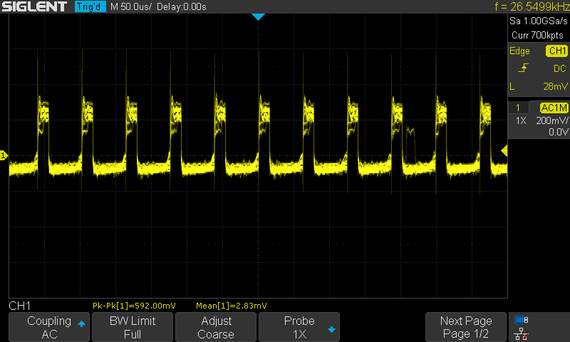
The higher the battery voltage, the more noisy the signal seems to be. It is probably caused by the RECOM DC/DC buck converter, whose output has only a 0.1uF cap? It should be 22 uF according to the spec sheet.
W/o passive filter, we got 40 mV noise at 33V battery voltage, and around 100 mV at 42V battery voltage. W/ passive filter, we get 4 mV and 12mV.
Cap to stabilize op amp output - bad idea!
https://electronics.stackexchange.com/questions/329917/capacitance-on-the-output-of-an-op-amp
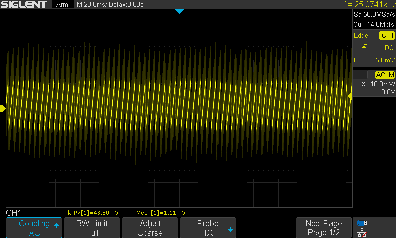
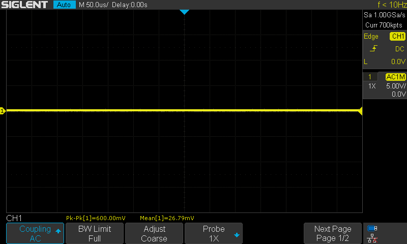
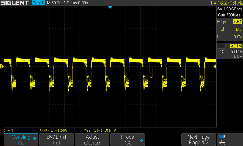
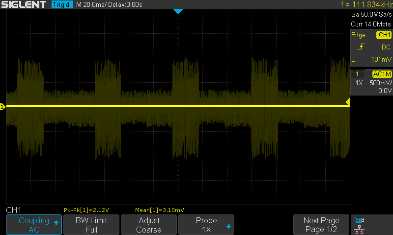
With the removed output cap, we got 50 mV noise on a 41.5V battery, no passive filter, but larger cap on the DC/DC converters. The noise is sawtooth signal. 5 sawtooth in 20 ms, so the period is 4 ms, so the frequency is 250 Hz.
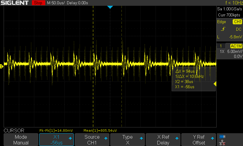
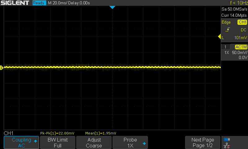
Adding the passive filter removes the sawtooth completely, a 10kHz noise remains. It is probably not the converters: the RECOM 12V DC/DC has 600 kHz operating frequency, the 3.3V one 650 kHz. They both inject noise for sure, max 100 mVpp, typical 40 mVpp.
Todo #2
- The board design must be updated to incorporate: (revision!!)
- corrected active filter
- add passive filter
- correct caps for DC/DC converters
- remove output cap from op-amp output
- fix all values written on the silkscreen
- The updated board design must be sent into production
- The two 'outdated' already assembled boards must be corrected to full spec
- Passive filter
- Software update
- Remove op-amp output cap
- Change cap in active filter
- TEST
- With correct resistors in the active filter gain
- The non-assembled board that are arriving soon (tomorrow?) must be assembled
- With correct cap values
- Omitting the op-amp output filter
- Adding the passive filter
- With correct resistors in the active filter gain
- They must be tested and added to the database
- The assembled boards that we already ordered must all be reworked after arrival
- Change SMD capacitor in active filter
- Remove SMD cap from op-amp output
- Add passive filter
- With correct resistors in the active filter gain
Test ride
Oscillations still present - 34-37, in the end jumped up to 39%. No percentage change during the ride of about 5 mins. In the end, jumped to 0%?!
Turns out it was badly assembled, the SOC wire slipped out. That could have caused the oscillation as well. Also a sense wire was damaged in the assembly process. New test needed.
Still oscillating 23-26%.
We notice that there is a lot of noise injected when the bike is pulling power. Also, when measured in-situ, the noise is around 90 mV - versus the 15 mV we measured on the bench! And removing the SOC wire from its plug makes no difference!! Turned out it was just the bad ground connection on the probe - now the noise is down to 20 mV!
Adding the signal ground
The board never powers on if it is connected only to the signal ground. Overall seems to make no difference at all.
Test drive again
No oscillations at all on the 36V battery at 35V.
Still oscillations at the 48V battery at 44V.
Oscillations still present when not pedaling.
Tuesday
First test of the day:
48V bike: no oscillations at 50V SOC, not even with the desktop supply connected at 2 or even 3A.
On drive: 63-60% when pedaling, oscillation. Jumped to 66% when stopped.
We try to update the software that rounds to 2%,
We tried to measure the noise injected by the bike controller.
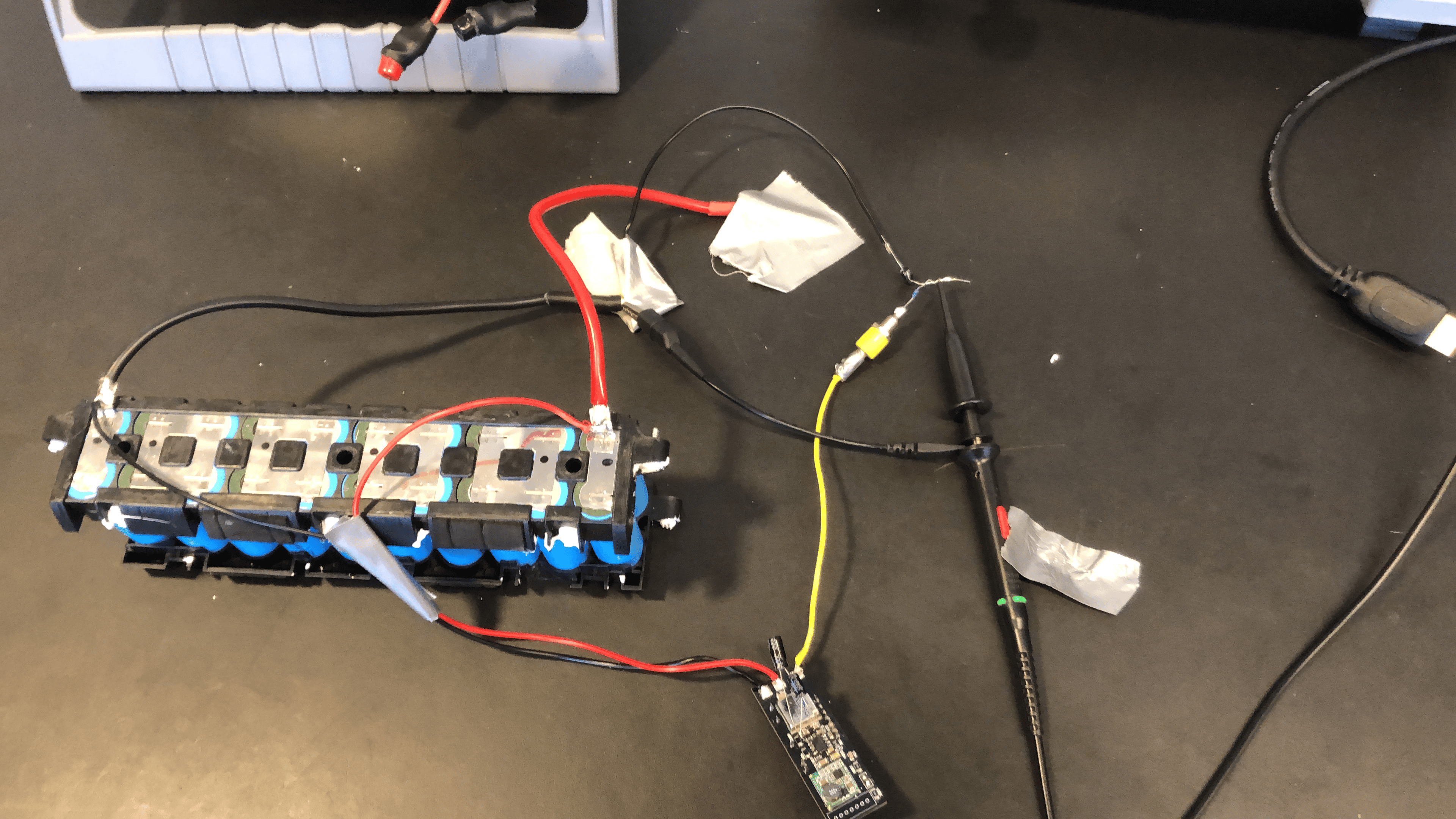
Setup: scope measured from B- to the white wire. The SOC output of our board is NOT connected. With and without pressing the walk assist:
If we measure between the 'signal ground' and the white wire, we get a lot more noise:
Measuring with the board plugged in - not spinning, unloaded spinning, loaded spinning:
Solving the grounding issue
One of the experiments we thought about was regarding the relative interconnection of the battery with the SoC board and the Chinese BMS. From the very beginning, the schematic was the following:
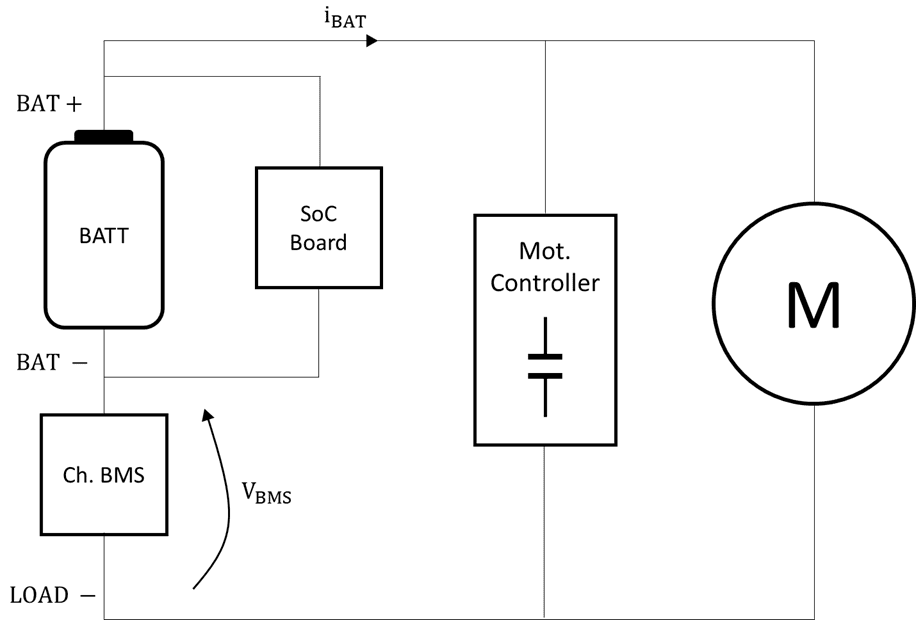
Notice that the possible mistake might be the different grounding levels of the overall system. Thus, when the motor begins to pull some current from the battery, the FET's internal resistance of the BMS (which are in the order of mOhm), will consequently produce a voltage drop on it, also in the order of mV, enough for introducing the previous oscillations on the SoC signal.
The proposed interconnection scheme ensures a solid ground (LOAD -) for all the system and apparently serves as the solution for the oscillation problematic. We just need to pull the SoC Board negative terminal from BAT - to LOAD - as depicted below.
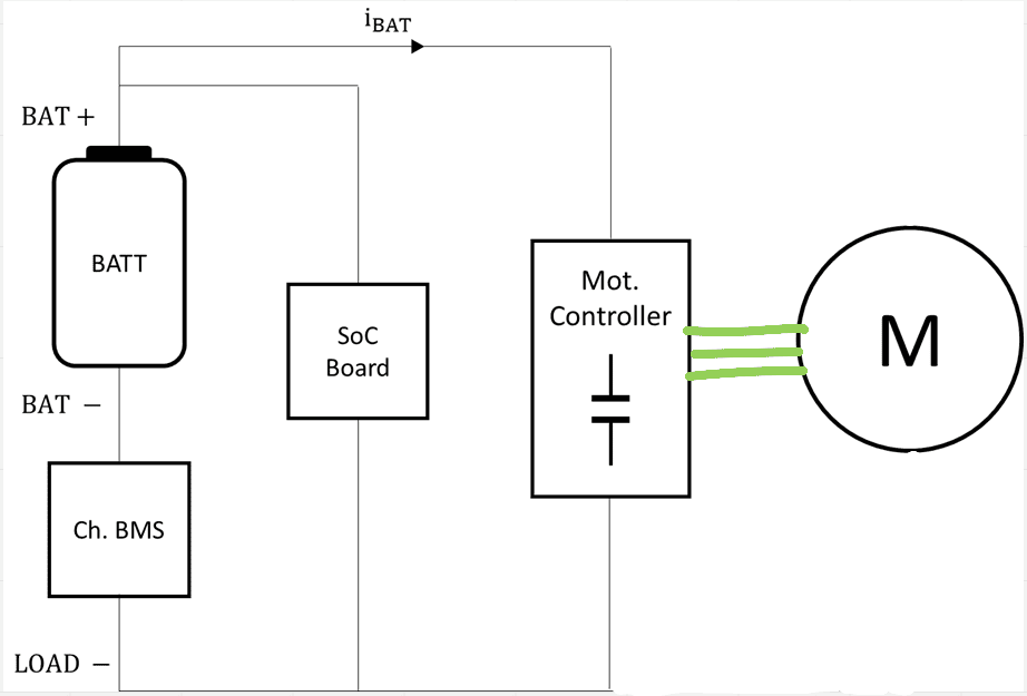
After trying this new connection scheme, the oscillation problem seems to have been mitigated both for 48 V and 36 V models.
There's still left to make some software modifications on the SoC signal. This is since, for the 36 V battery, for a 41.7 V level it displayed 90%, which is absolutely wrong. Next steps will go through this problematic.
11/08 -> display problem solved
Assembled version
For the BH assembled board, we have made the same procedure than before. We have included an RC output filter to decrease the noise ripple.
The values and result are:
RC = 3.3 kOhm * 220 uF ---> 10.4 mV ripple.
However, maybe the measurement was being contaminated because a bad connection of the oscilloscope prove.
Next step is to try the previous values RC = 3.3 kOhm * 33 uF.
Solution
R = 3.3 kOhm
C = 33 uF
It was a bad measurement!!!!!
No comments to display
No comments to display