
Concept: reverse engineered Yamaha battery
Source: https://endless-sphere.com/forums/viewtopic.php?t=70198
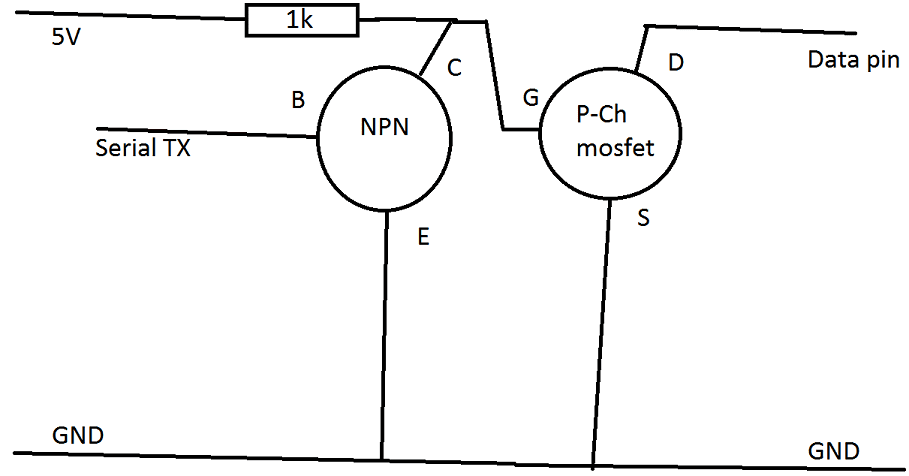
Quote: An Arduino compatible board and a few discrete components
Add a 5V source, i usually use a LM2596HV dc dc converter for this. A USB powerbank or even running it from two or three Cells on the pack (VIN pin of the arduino) will work.
Optional: To monitor the voltage add a voltage divider set to a ratio of 7.401 (42v in 5v out) and connect it to the A0 pin of the Arduino.
Edit this code https://pastebin.com/34SdehGt
>Edit line 35 to match your voltage divider. calculate or test to find out ADC values.
>Change line 44 and 45 (the number 20) to a value you want. 20 means it averages the current voltage 20 times to smooth it out. 20 is 5 seconds.
>Remove line 50 if you dont want your indicator to stay at 10% even if its lower. this prevent turning the motor off when voltage drops driving up a hill.
After that, Flash it in Arduino IDE
Wire it up like this.
Some people including me already did it to the haibikes, works great. See german pedelecforum.
If its too much for you, a guy called Cosas in pedelecforum is selling modules based off my code that does exactly this, basically dongles you put on the Battery connector and can connect any ordinary 36V Battery onto it.
Code
//255 255 14 6 26 25 1 110 2 199 42 248 1 24 17 192 0 110 7
int b1=255;
int b2=255;
int b3=14;
int b4=6;
int b5 = 100;//batt percent.
int b6=25;
int b7=1;
int b8=110; //??
int b9=2; //?? 2-3
int b10=199; // ?? 22-255
int b11=42;
int b12=248;
int b13=1;
int b14=24;
int b15=17;
int b16=240; //unusedled indicator 128-192-240-255
int b17=0; // 0-7 prob. power
int b18=110; // 0-255
int b19;
int b5t = 0;
int b5t2 = 0;
int index = 0;
boolean low = false;

void setup(){
  Serial.begin(2400,SERIAL_8E1);
}

void loop(){
    // this shit here is linear, dont expect a fancy li-ion charge algorithm.
    b5t = (int)map(analogRead(0),804,1023,0,100);
    //calibrate here.
    //804 = 3.93V Analog In = empty @ 33V batt
    //1023 = 5V Analog In =  full @ 42V batt
    b5t2 = b5t2 + b5t;
    index = index + 1;
    // averaging, calc every 5 secs a new batt percentage.
    if(index > 20){
        b5 = (int)(b5t2 / 20);
        b5t2 = 0;
        index = 0;
    }
    if(b5 >= 100){ b5 = 100; }
    if(b5 <= 10 || low){ b5 = 10; low = true;}
    //once it goes below 10% stay there until Arduino has been restarted.
    //voltage drop cause the motor to turn off on a hill.
    //this squeezes the last bit of juice out of your batt.

    //crc sum dont change
    b19 = ((b1-b2-b3-b4-b5-b6-b7-b8-b9-b10-b11-b12-b13-b14-b15-b16-b17-b18)%256)+256;

    // 4x a sec, dont change or add any other delay.
    delay(250);
    Serial.write(b1);
    Serial.write(b2);
    Serial.write(b3);
    Serial.write(b4);
    Serial.write(b5);
    Serial.write(b6);
    Serial.write(b7);
    Serial.write(b8);
    Serial.write(b9);
    Serial.write(b10);
    Serial.write(b11);
    Serial.write(b12);
    Serial.write(b13);
    Serial.write(b14);
    Serial.write(b15);
    Serial.write(b16);
    Serial.write(b17);
    Serial.write(b18);
    Serial.write(b19);
}
Customized application
The aid was to develop our own State of Charge algorithm such as we did for the BH battery, however this time the data must be transmitted to the motor controller through a SCI (UART) communication following the above description found on the internet.
The battery communicates via an asynchronous serial data connection, where the drive unit sets the signal pin to 5V, and the battery pulls it back to GND while sending the signal. The serial connection consists of 8 bit characters, "Even parity bit" and 1 stop bit. Baud rate is 2400 Hz.
- The battery sends data to the drive unit
- The drive unit does not send data to the battery
- The battery sends a 19 bytes data packet every 160 ms, each consisting of 8 bit characters
- The signal voltage is 5V, where signal must be drawn to GND when transmitting.
Data back and forth
B1  - 255     /   Unknown    / fixed
B2  - 255     /   Unknown    / fixed
B3  - 14      /   Unknown    / fixed
B4  - 6       /   Unknown    / fixed
B5  - 0-100   /   SoC in %   / dynamic
B6  - 25      /   Unknown    / fixed
B7  - 1       /   Unknown    / fixed
B8  - 110-169 /   Unknown    / dynamic
B9  - 2-3     / Temperature  / dynamic
B10 - 22-199  /   Voltage    / dynamic
B11 - 42      /   Unknown    / fixed
B12 - 248     /   Unknown    / fixed
B13 - 1       /   Unknown    / fixed
B14 - 24      /   Unknown    / fixed
B15 - 17      /   Unknown    / fixed
B16 - 192-240 /   Unknown    / dynamic
B17 - 0-6     /   Power I    / dynamic
B18 - 0-255   /   Power II   / dynamic
B19 - 0-255   /   Checksum   / dynamic
Fixed = value remained the same in all measurements
Dynamic = value changed during the measurement
- B9 could be responsible for the temperature alert
- B10 could be related with battery voltage
- B17 and B18 could be related with Power (current) withdrawal
- Byte 19 can be calculated exactly with:
B19 = (B1 - B2 - B3 - B4 - B5 - B6 - B7 - B8 - B9 - B10 - B11 - B12 - B13 - B14 - B15 - B16 - B17 - B18) % 256
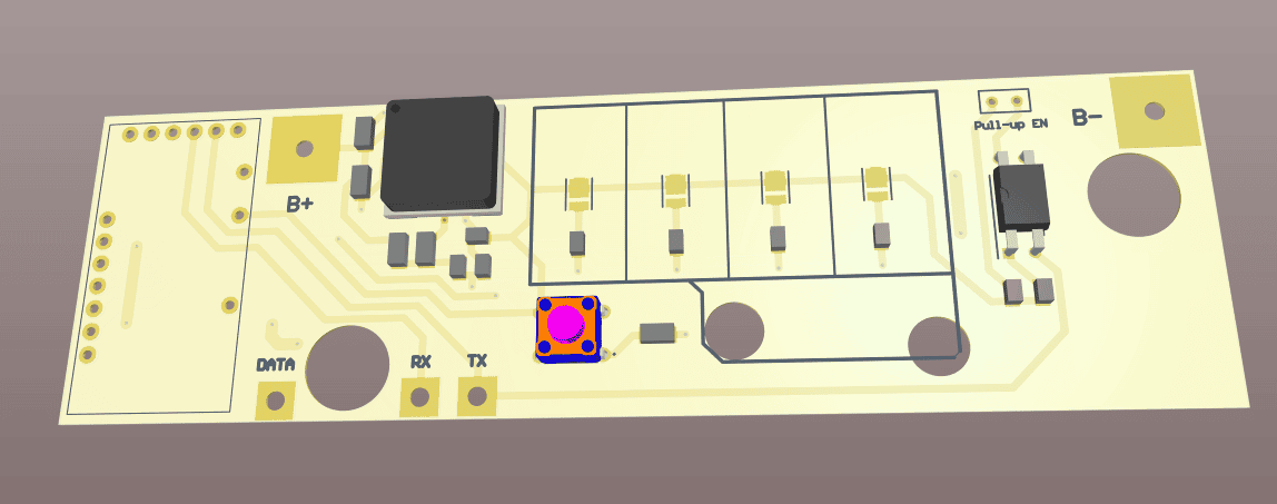
Design
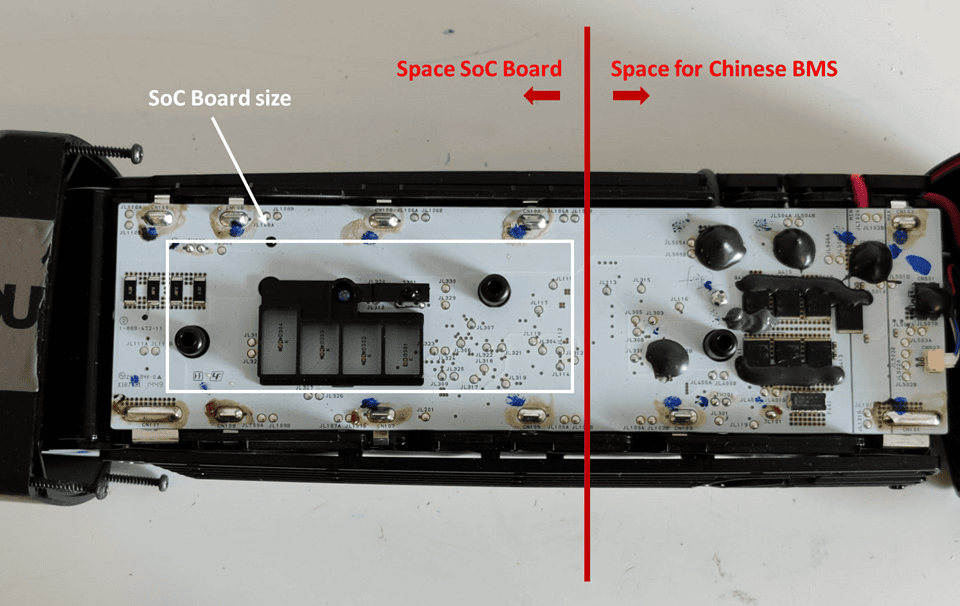
The objective is to substitute the Yamaha's own battery BMS with a Daly one. However, we must recreate the SoC indicator part, since it doesn't include that feature. The available space in the package would hold a PCB of 22 x 6 cm, and it will be distributed as indicated in the picture.
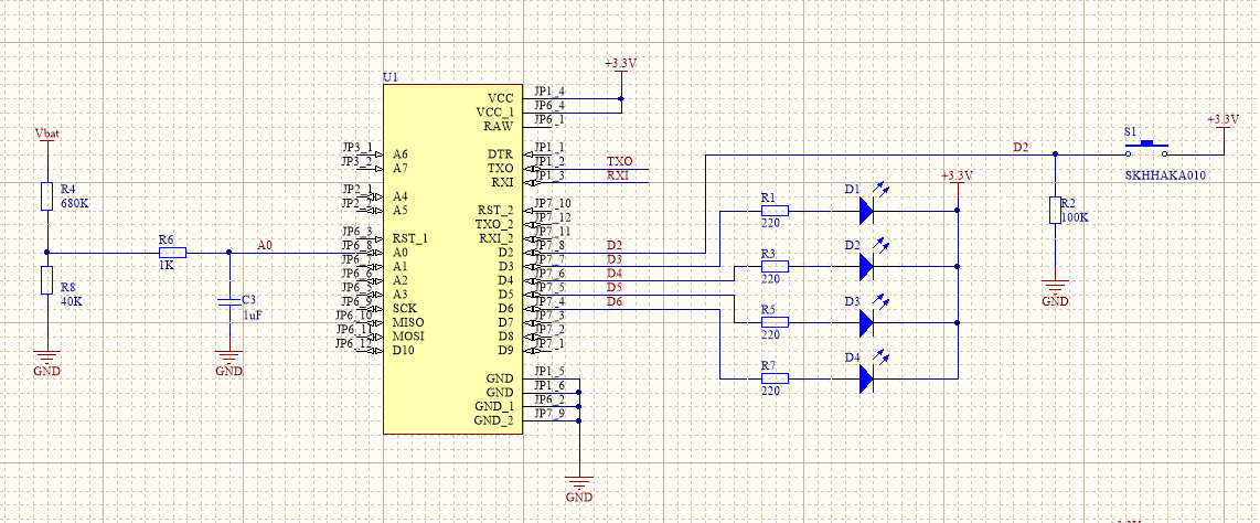
We will use the Arduino Pro Mini for the control of the circuit. It will be in charge of computing the battery SoC, communicating via UART and indicating it through four LED's. The same voltage divider will be used as in the BH indicator project, and it will serve as an input for the battery voltage measurement. Also, a switching regulator based on a DC-DC is used for the main supply (60V to 3.3V).
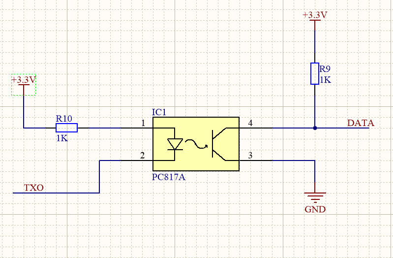
Finally, the previously discussed NPN Transistor and P Channel Mosfet has been replaced with an optocoupler as seen in the screenshot below. In particular the "PC817A". This will ensure that the output data is refereed to a solid GND (still needed to know if Vcc = +3.3V or +5.0V).
The size of this board is 3.5 x 12 cm. Thus, the 3D render of this board can be seen below. The design has been done respecting the holes and the LED's holder and push-button position. Also, the pushbutton must be 5mm tall. It is the only height that truly fits inside the package. It will be from the SKHH family available on Mouser.
Code employed 28/07 - Only communication part
// Verified for Arduino Nano Every. 27/07/2021
// Communication of the SOC through UART
// Next step... LED's indicators

int msg[19] = {254,254,14,6,100,25,1,110,2,199,42,248,1,24,17,240,0,110,7}; // Message initialization
int i = 0;
float meas, voltage, vbat; // Main SOC variables
float SOC;                 // SoC signal variable
const int R1 = 680;        // Voltage divider R1
const int R2 = 40;         // Voltage divider R1
int aux = 0;               // Auxiliar variable for check-sum

void setup(){
  Serial.begin(9600);
  Serial1.begin(2400, SERIAL_8E1);
}

void loop(){
 meas = analogRead(A0);               // Read ADC
 voltage = meas * 5.0 / 1024;         // Compute voltage
 vbat = voltage * (R1 + R2) / R2;     // Battery voltage translation
 SOC = computeSOC_36v(vbat);          // SOC Determination

 /* Signal limiting */
 if (SOC < 0.05) {
    SOC = 0.01;
 }
 else if (SOC > 0.95) {
    SOC = 1;
 }

 /* Byte 5 for the SoC signal */
 msg[4] = 100 * SOC;

 /* Check-sum at byte 19 */
 for (i = 0; i < 18; i++) {
    aux = msg[i] - msg[i - 1];
 }
 msg[18] = 256 + (aux % 256);

 /* Sending data */
 for (int j = 0; j < 18; j++) {
    Serial1.write(msg[j]);
 }
 delay(250);
}

float computeSOC_36v(float X) {
    float Y;
    if (X < 33.5) {
         Y = (0.15 - 0.0) / (33.5 - 28.0) * (X - 28.0) + 0.0;
    }
    else if ((X >= 33.5) && (X < 36.5)) {
         Y = (0.5 - 0.15) / (36.5 - 33.5) * (X - 33.5) + 0.15;
    }
    else if ((X >= 36.5) && (X < 39.9)) {
         Y = (0.87 - 0.5) / (39.9 - 36.5) * (X - 36.5) + 0.5;
    }
    else if (X >= 39.9) {
         Y = (1.0 - 0.87) / (42.0 - 39.9) * (X - 39.9) + 0.87;
    }
    return Y;
}
Results
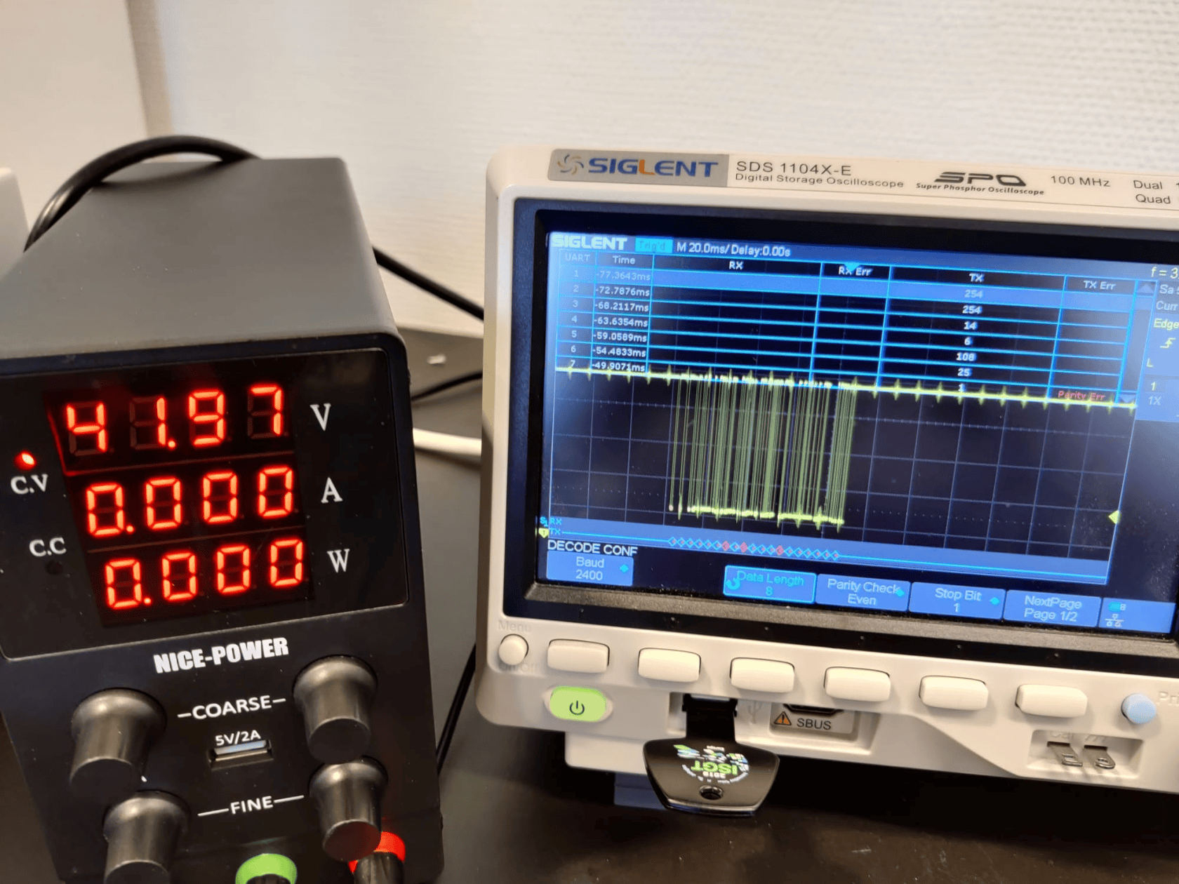
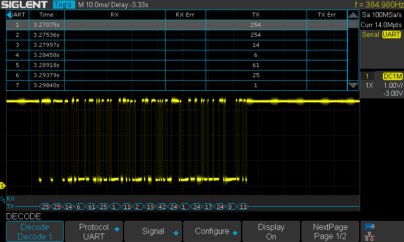
After computing the SoC and transmitting it through UART with the previous code, the communication has been verified using Arduino Nano Every and the oscilloscope result can be seen below.
The byte number 5 contains the SoC is on 100, which corresponds to the 100% battery capacity.
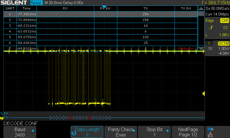
Byte 5 at 108 (need a bit calibration) when V = 42V.
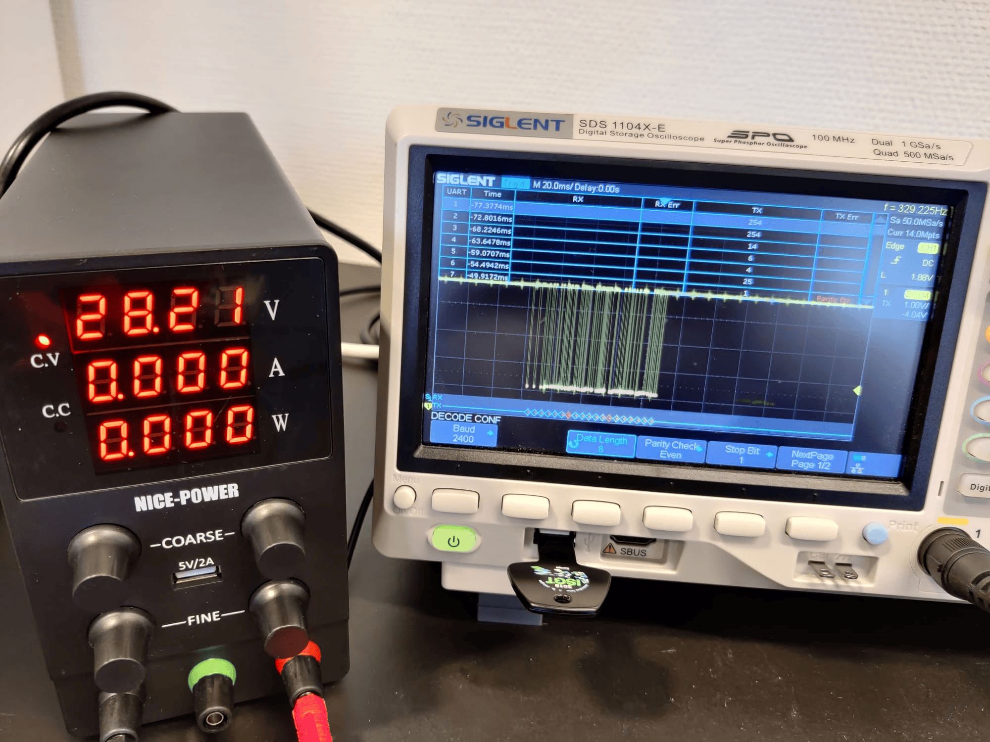
Byte 5 at 6 when V = 28V.
The rest of the bytes remain good.
Custom PCB results
After producing the previous circuit board, it has been set-up using the source and the oscilloscope as in the following picture,
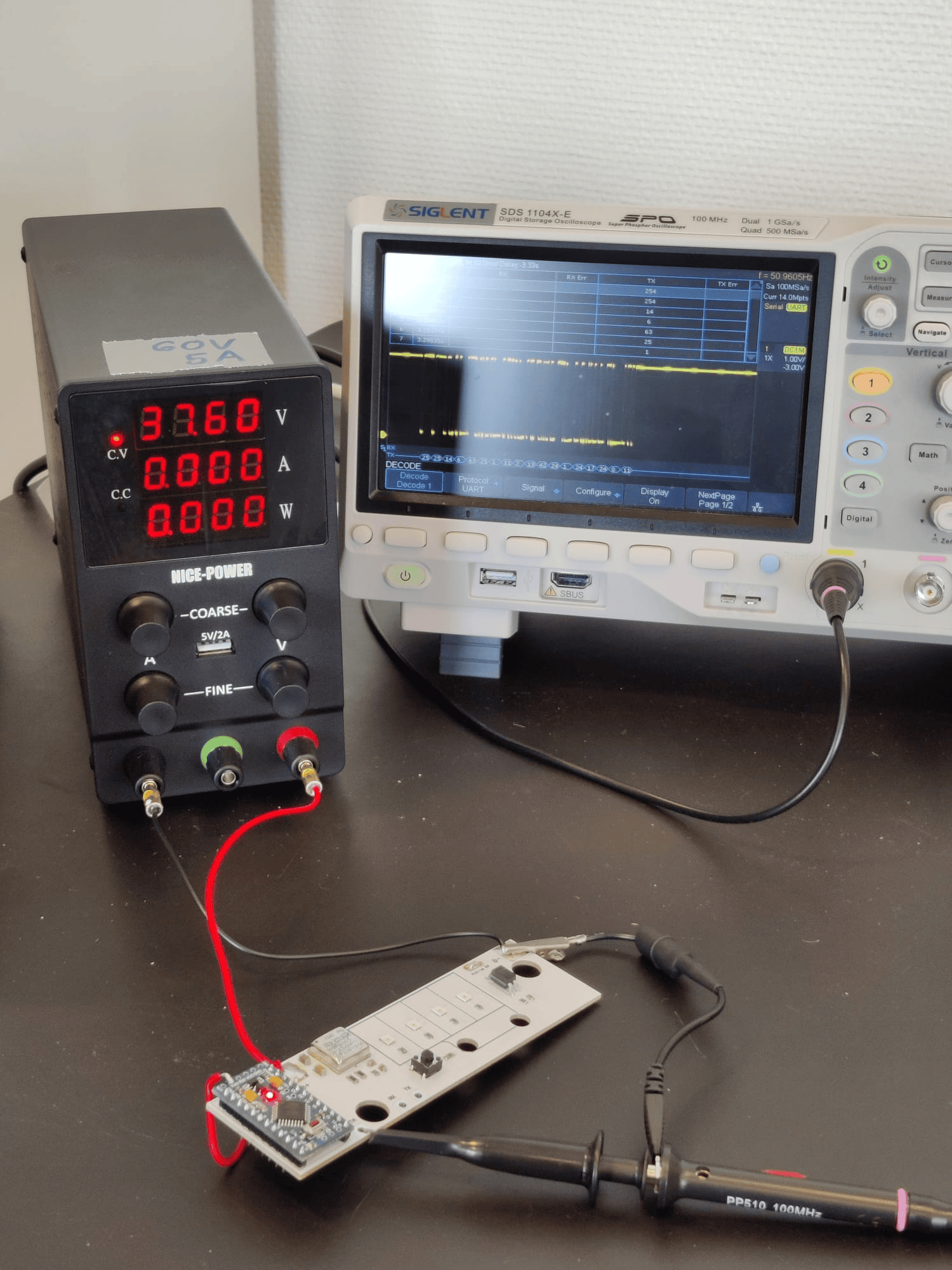
The result obtained can be seen below too.
Notice that this time the quality of the communication has been improved. This is related to the improvement of the PCB quality.
// Communication of the SOC through UART
// Verified for Arduino Pro Mini, 29/07/2021
// Verified at all in PCB, 04/08/2021

/* SCI Variables Initialization */
int j = 0;
int i = 0;
int aux = 0;      // Auxiliar variable for check-sum
byte msg[19] = {254, 254, 14, 6, 100, 25, 1, 110, 2, 199, 42, 248, 1, 24, 17, 240, 0, 110, 7}; // Message initialization

/* SoC Variables Initialization */
float meas, voltage, vbat; // Main SOC variables
float SOC;                 // SoC signal variable
const int R1 = 680;        // Voltage divider R1
const int R2 = 40;         // Voltage divider R1

/* LED Indicator Initialization */
int Button = 2;           // LED's trigger   (D02)
int LED1 = 3;             // LED1 pin to use (D03)
int LED2 = 4;             // LED2 pin to use (D04)
int LED3 = 5;             // LED3 pin to use (D05)
int LED4 = 6;             // LED4 pin to use (D06)

int State_LED1 = HIGH;    // LED 1 Status
int State_LED2 = HIGH;    // LED 2 Status
int State_LED3 = HIGH;    // LED 3 Status
int State_LED4 = HIGH;    // LED 4 Status

int StateButton;
int lastStateButton = 0;
unsigned long T_Control = 0;   // Controls time spent
unsigned long T_Off = 5000;    // Time working in ms

void setup() {

  Serial.begin(2400, SERIAL_8E1);

  pinMode(LED1, OUTPUT);    // Set pin 2 as LED output
  pinMode(LED2, OUTPUT);    // Set pin 3 as LED output
  pinMode(LED3, OUTPUT);    // Set pin 4 as LED output
  pinMode(LED4, OUTPUT);    // Set pin 5 as LED output

  pinMode(Button, INPUT);   // Set pin 2 as Button input

  digitalWrite(LED1, HIGH);
  digitalWrite(LED2, HIGH);
  digitalWrite(LED3, HIGH);
  digitalWrite(LED4, HIGH);
}

void loop() {

  meas = analogRead(A0);               // Read ADC
  voltage = meas * 3.3 / 1023;         // Compute voltage
  vbat = voltage * (R1 + R2) / R2;     // Battery voltage translation

  SOC = computeSOC_36v(vbat);          // SOC Determination

  /* Signal limiting */
  if (SOC < 0.05) {
    SOC = 0.01;
  }
  else if (SOC > 0.95) {
    SOC = 1;
  }

  /* Byte 5 for the SoC signal */
  msg[4] = 100 * SOC;

  /* Check-sum at byte 19 */
  msg[19] = ((msg[1]-msg[2]-msg[3]-msg[4]-msg[5]-msg[6]-msg[7]-msg[8]-msg[9]-msg[10]-msg[11]-msg[12]-msg[13]-msg[14]-msg[15]-msg[16]-msg[17]-msg[18])%256)+256;

  /* Sending data */
  for (j = 0; j < 18; j++) {
    Serial.write(msg[j]);
  }

  delay(250);

  if ((SOC >= 0) && (SOC <= 0.25)) {
    State_LED1 = HIGH;
    State_LED2 = HIGH;
    State_LED3 = HIGH;
    State_LED4 = LOW;

  }
  else if ((SOC > 0.25) && (SOC <= 0.5)) {
    State_LED1 = HIGH;
    State_LED2 = HIGH;
    State_LED3 = LOW;
    State_LED4 = LOW;
  }
  else if ((SOC > 0.5) && (SOC <= 0.75)) {
    State_LED1 = HIGH;
    State_LED2 = LOW;
    State_LED3 = LOW;
    State_LED4 = LOW;
  }
  else if ((SOC > 0.75) && (SOC <= 1.0)) {
    State_LED1 = LOW;
    State_LED2 = LOW;
    State_LED3 = LOW;
    State_LED4 = LOW;
  }

  StateButton = digitalRead(Button);    // Read pushbutton
  if (lastStateButton != StateButton)   // Did I press it ??
  {
    T_Control = millis() + T_Off;       // Start computing time to turn off (in milli-seconds)
    // ACTIVE LEDs
    digitalWrite(LED1, State_LED1);
    digitalWrite(LED2, State_LED2);
    digitalWrite(LED3, State_LED3);
    digitalWrite(LED4, State_LED4);
  }
  lastStateButton = StateButton;
  if (millis() > T_Control && T_Control > 0) // Was it time for turning off?
  {
    // DEACTIVE LEDs
    digitalWrite(LED1, HIGH);
    digitalWrite(LED2, HIGH);
    digitalWrite(LED3, HIGH);
    digitalWrite(LED4, HIGH);
    T_Control = 0;                          // Stop controlling
  }
}

float computeSOC_36v(float X) {
  float Y;
  if (X < 33.5) {
    Y = (0.15 - 0.0) / (33.5 - 28.0) * (X - 28.0) + 0.0;
  }
  else if ((X >= 33.5) && (X < 36.5)) {
    Y = (0.5 - 0.15) / (36.5 - 33.5) * (X - 33.5) + 0.15;
  }
  else if ((X >= 36.5) && (X < 39.9)) {
    Y = (0.87 - 0.5) / (39.9 - 36.5) * (X - 36.5) + 0.5;
  }
  else if (X >= 39.9) {
    Y = (1.0 - 0.87) / (42.0 - 39.9) * (X - 39.9) + 0.87;
  }
  return Y;
}
Also, the LED indicator is working fine. The code employed and final version of itself is the following.
Battery implementation
Finally, the prototype has been implemented in a real battery for testing. The set-up is shown in the picture, where, for a battery voltage of 30 V, the fifth byte displays a SoC = 5%. Also, only one of the LED's is shining.
No comments to display
No comments to display