
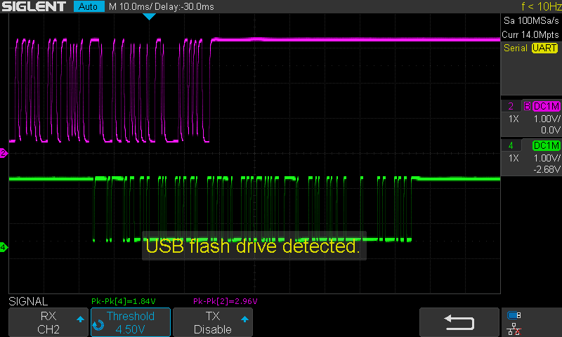
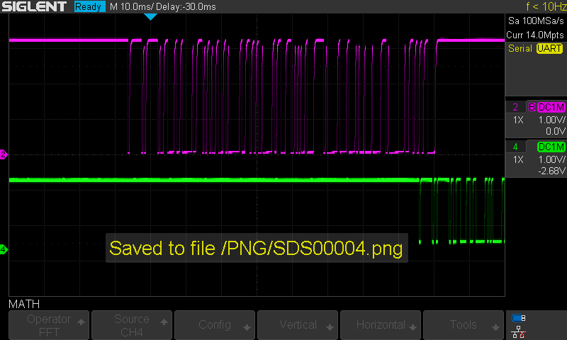
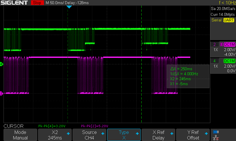
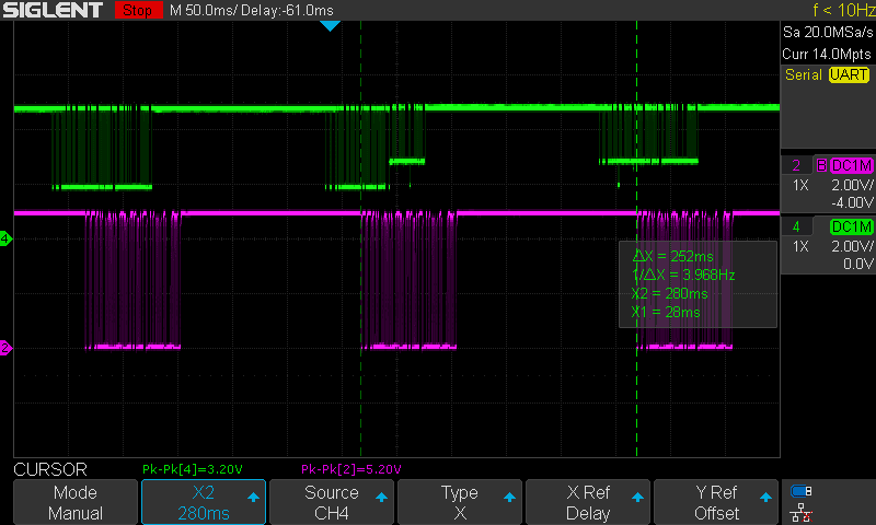
Tuning the data output
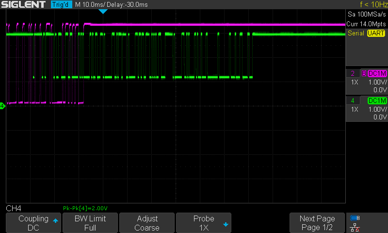
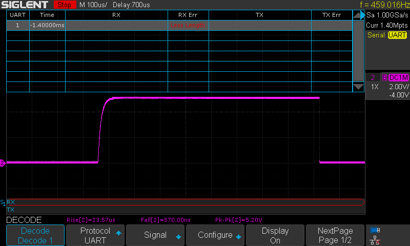
Purple trace: Yedlik board
Green trace: original board
We attached a 10k pull-up resistor to 3.3V to each battery's middle pin. 3.3V is supplied by separate desktop power supplies.
Tuning the pull-up resistor value
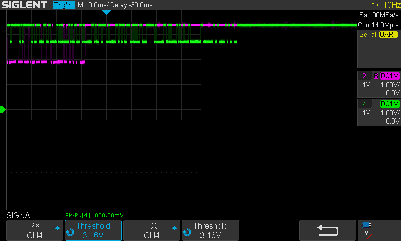
The original board's output amplitude is too low, and the Yedlik board's output is distorted. We try with 1k pull-up:
It got worse. We need more resistance, not less! Trying with 51k:
51k gives the same as 10k. No benefit at all.
Tuning the optocoupler's input resistor
In all the previous tests, it was 1k. With 10k:
With 6.8k:
With 470 Ohm:
Charging it to 100Ohm made no difference:
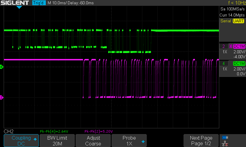
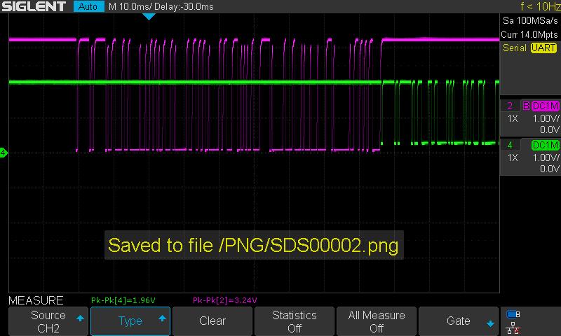
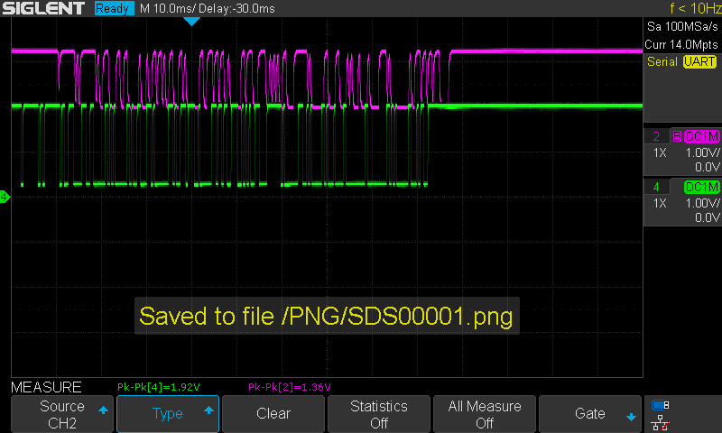
The original battery on the bike vs the Yedlik pulled to 5V
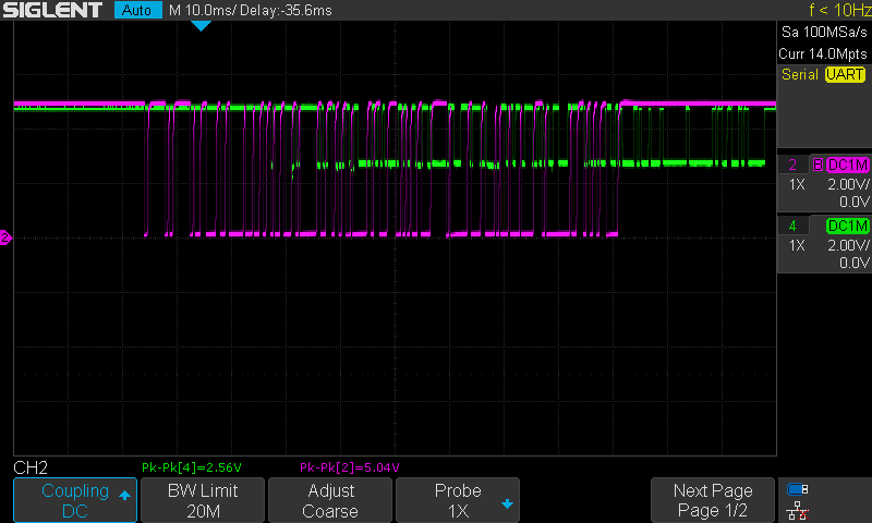
We learned that the bike uses a 5V system, but that there is some resistance probably on the battery side in the data line so that when the data pin is pulled to 5V, it cannot go to zero.
We noticed that the signals are moving in phase compared to each other - the delay is not accurate!!! Only 2ms difference it seems.
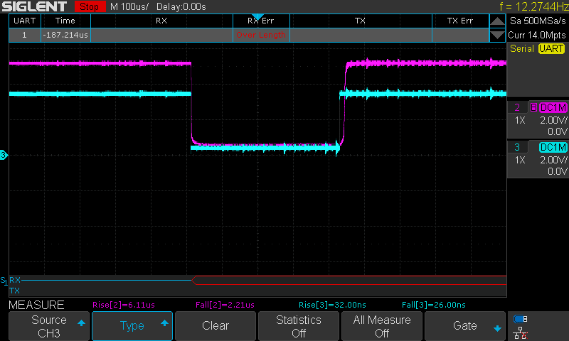
Adding series resistor after optocoupler
Adding a 470 Ohm resistor in series with the data pin made the signal a lot more 'square'. But still not good enough, and hence the problem. Even the scope can't decode it! Too slow rise time. Below the screenshots compare the output and the input of the optocoupler.
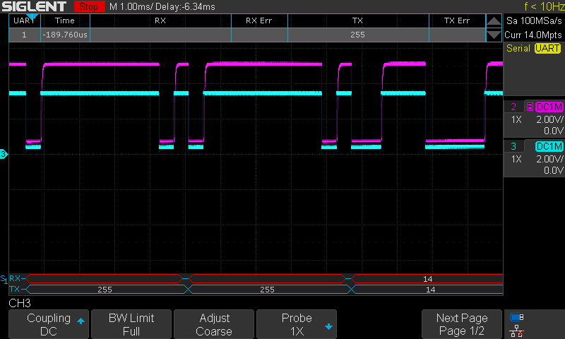
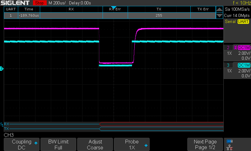
In fact the fall time is okay, but the rise time is bad!!
Taken out of the bicycle, just comparing the speed on the input and output of the optocoupler:
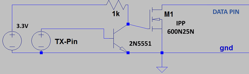
Substituting the optocoupler by BJT + MOSFET
The following circuit has been recreated. All values and devices employed can be seen in the picture.
There has been an improvement on the quality signal. This time the data has much more better squared shape. However, bytes 1 and 2 still not good enough and the bike doesn't seem to turn on.
The following scope has been obtained when measuring the battery data pin plugged in the bike.
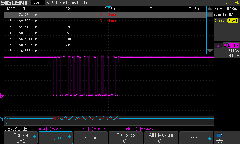
It also looks like the mosfet could be bad quality. Its output is worse quality in comparison to is gate signal provided by the BJT.
BJT output and MOSFET gate signal. Turning on looks fast
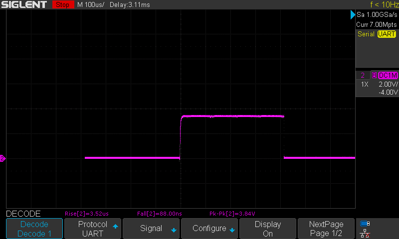
MOSFET drain signal (data pin). Looks slower.
Two things can be tested for improving:
- Placing a clamping resistor (10k) between the mosfet gate and source
- Definitely using other mosfet with better specifications
The solution
The solution has been done in two steps. Firstly, the mosfet has been substituted by a BJT, exactly the same than the one we already use. Then the quality of the signal was much better. However, the bike still didn't respond.
In the end, after reviewing the code, a typo in the message array was denying the byte 19 to be transmitted correctly (remember that the position 0 in the array matters!). The code has been updated.
// Communication of the SOC through UART
// Verified for Arduino Pro Mini, 29/07/2021
// Verified at all in PCB, 04/08/2021

/* SCI Variables Initialization */
int j = 0;
int i = 0;
int aux = 0;      // Auxiliar variable for check-sum
byte msg[19] = {255, 255, 14, 6, 100, 25, 1, 110, 2, 199, 42, 248, 1, 24, 17, 240, 0, 110, 7}; // Message initialization

/* SoC Variables Initialization */
float meas, voltage, vbat; // Main SOC variables
float SOC;                 // SoC signal variable
const int R1 = 680;        // Voltage divider R1
const int R2 = 40;         // Voltage divider R1

/* LED Indicator Initialization */
int Button = 2;           // LED's trigger   (D02)
int LED1 = 3;             // LED1 pin to use (D03)
int LED2 = 4;             // LED2 pin to use (D04)
int LED3 = 5;             // LED3 pin to use (D05)
int LED4 = 6;             // LED4 pin to use (D06)

int State_LED1 = HIGH;    // LED 1 Status
int State_LED2 = HIGH;    // LED 2 Status
int State_LED3 = HIGH;    // LED 3 Status
int State_LED4 = HIGH;    // LED 4 Status

int StateButton;
int lastStateButton = 0;
unsigned long T_Control = 0;   // Controls time spent
unsigned long T_Off = 5000;    // Time working in ms

void setup() {

  Serial.begin(2400, SERIAL_8E1);

  pinMode(LED1, OUTPUT);    // Set pin 2 as LED output
  pinMode(LED2, OUTPUT);    // Set pin 3 as LED output
  pinMode(LED3, OUTPUT);    // Set pin 4 as LED output
  pinMode(LED4, OUTPUT);    // Set pin 5 as LED output

  pinMode(Button, INPUT);   // Set pin 2 as Button input

  digitalWrite(LED1, HIGH);
  digitalWrite(LED2, HIGH);
  digitalWrite(LED3, HIGH);
  digitalWrite(LED4, HIGH);
}

void loop() {

  meas = analogRead(A0);               // Read ADC
  voltage = meas * 3.3 / 1023;         // Compute voltage
  vbat = voltage * (R1 + R2) / R2;     // Battery voltage translation

  SOC = computeSOC_36v(vbat);          // SOC Determination

  /* Signal limiting */
  if (SOC < 0.05) {
    SOC = 0.01;
  }
  else if (SOC > 0.95) {
    SOC = 1;
  }

  /* Byte 5 for the SoC signal */
  msg[4] = 100 * SOC;

  /* Check-sum at byte 19 */
  msg[18] = ((msg[0]-msg[1]-msg[2]-msg[3]-msg[4]-msg[5]-msg[6]-msg[7]-msg[8]-msg[9]-msg[10]-msg[11]-msg[12]-msg[13]-msg[14]-msg[15]-msg[16]-msg[17])%256)+256;

 // Serial.println("Message: ");
  /* Sending data */
  for (j = 0; j < 19; j++) {
    Serial.write(msg[j]);
    //Serial.println(msg[j]);
  }

  delay(250); // 250

  if ((SOC >= 0) && (SOC <= 0.25)) {
    State_LED1 = HIGH;
    State_LED2 = HIGH;
    State_LED3 = HIGH;
    State_LED4 = LOW;

  }
  else if ((SOC > 0.25) && (SOC <= 0.5)) {
    State_LED1 = HIGH;
    State_LED2 = HIGH;
    State_LED3 = LOW;
    State_LED4 = LOW;
  }
  else if ((SOC > 0.5) && (SOC <= 0.75)) {
    State_LED1 = HIGH;
    State_LED2 = LOW;
    State_LED3 = LOW;
    State_LED4 = LOW;
  }
  else if ((SOC > 0.75) && (SOC <= 1.0)) {
    State_LED1 = LOW;
    State_LED2 = LOW;
    State_LED3 = LOW;
    State_LED4 = LOW;
  }

  StateButton = digitalRead(Button);    // Read pushbutton
  if (lastStateButton != StateButton)   // Did I press it ??
  {
    T_Control = millis() + T_Off;       // Start computing time to turn off (in milli-seconds)
    // ACTIVE LEDs
    digitalWrite(LED1, State_LED1);
    digitalWrite(LED2, State_LED2);
    digitalWrite(LED3, State_LED3);
    digitalWrite(LED4, State_LED4);
  }
  lastStateButton = StateButton;
  if (millis() > T_Control && T_Control > 0) // Was it time for turning off?
  {
    // DEACTIVE LEDs
    digitalWrite(LED1, HIGH);
    digitalWrite(LED2, HIGH);
    digitalWrite(LED3, HIGH);
    digitalWrite(LED4, HIGH);
    T_Control = 0;                          // Stop controlling
  }
}

float computeSOC_36v(float X) {
  float Y;
  if (X < 33.5) {
    Y = (0.15 - 0.0) / (33.5 - 28.0) * (X - 28.0) + 0.0;
  }
  else if ((X >= 33.5) && (X < 36.5)) {
    Y = (0.5 - 0.15) / (36.5 - 33.5) * (X - 33.5) + 0.15;
  }
  else if ((X >= 36.5) && (X < 39.9)) {
    Y = (0.87 - 0.5) / (39.9 - 36.5) * (X - 36.5) + 0.5;
  }
  else if (X >= 39.9) {
    Y = (1.0 - 0.87) / (42.0 - 39.9) * (X - 39.9) + 0.87;
  }
  return Y;
}
The bike now seems to respond, no place for errors anymore. Next step will be to try a ride and see if it withstands.
No comments to display
No comments to display