
Lowering consumption, Part 1: hardware
Baseline
Current consumption, with the transistors disconnected:
- 9.82 mA @ 30V
- 7.5 mA @ 42V
Interestingly, if I put the Arduino to powerDown all the time, it still consumes 7.13 mA @ 42V.
The RECOM RPMH-0.5 3.3V fix output DC/DC converter has only 16 uA quiescent current at 48V. (Max 50 uA)
Removing components
Removing the SMD resistors under the transistors: very little difference. Now it is:
- 8.89 mA @ 30V
- 6.85 mA @ 42V.
Cutting off the transistors: exactly the same. No help.
Removing a 220 Ohm resistor to cut off an LED: same.
Removing the 680K:
- 8.7 mA @ 30V
- 6.64 mA @ 42V
Removing the input caps: same.
Removing output caps: same.
Removing all the LEDs, and the button pull down: same.
Measuring a good RECOM alone
- 12 uA @ 30V
- 11 uA @ 42V
Attaching that RECOM to the board
- 6.84 mA @ 42V
Using the same RECOM with a different Arduino Pro Mini without the Yamaha board: 200 to 400 uA!!! (measured with Biltema multimeter)
Solution
A7 of the Arduino was shorted to the ground on the Yamaha board V1 - that caused the high power consumption.
There's a difference between "A7" and pin number 7. None of them are shorted to ground. Please, see layout below.
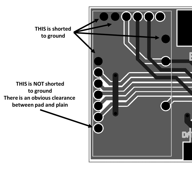
That pin is used only to have a more strong attachment of the Arduino to the PCB, but in the end, that pin is flotating, just as all the ones not being used.
Putting back components
With all components, excluding the transistors:
- 258 to 435 uA on biltema meter @ 41.6V battery
- 3.4 mA when the 4 LEDs are on
With the two BJTs back on, displayed on the Biltema meter:
- 686 to 927 uA @ 30V supply
- 550 to 723 uA @ 42V supply
This is 300 uA more.
3.293 mA should be the consumption at 3.3V according to CircuitLab. That is 320 uA at 42V assuming 80% efficiency.
Also the base of the first BJT needs to be current limited!!
Simulation and implementation
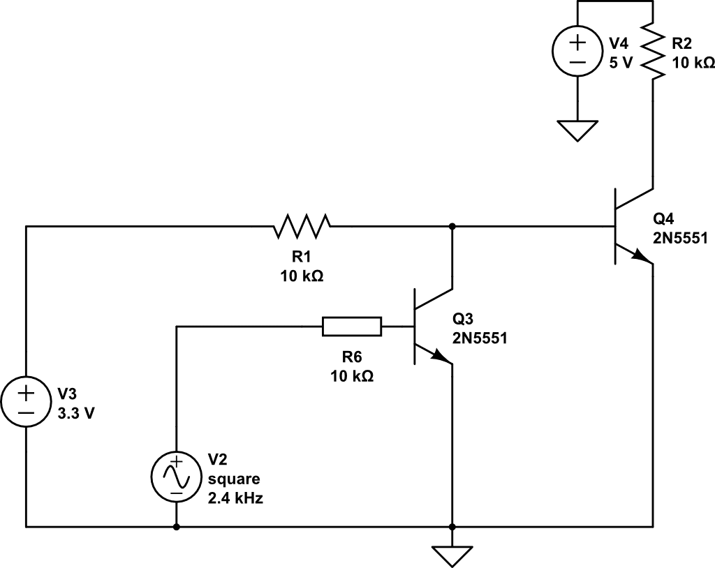
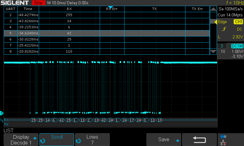
This worked, and produced a clean signal:
Could we have it with higher resistance for R6?
100k: Works in simulation, but no output IRL.
20k: Works perfect!
Will it work with 1k pull-up (R2)?
We don't know what is really there in the bike, so we want to experiment. Simulation says it should work, reality is a NO.
We try going to R6=10k. (But probably R1 is the key variable here?) No luck.
Let's try making R1=2.2k!
Weird, the signal is still low amplitude, but different.
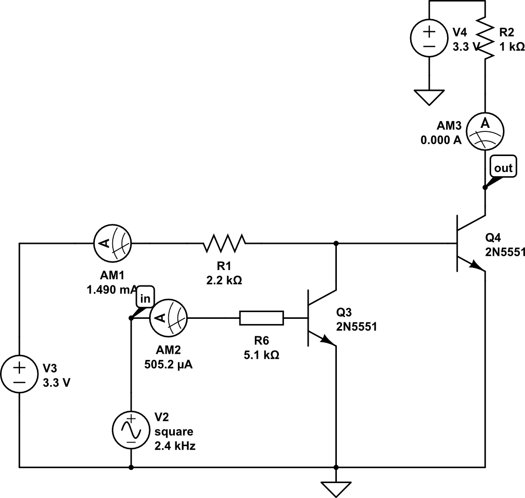
We try now making R6=5.1k. -WORKS!
Final
Built 2 pcs, works on the bike as well! :)
The consumption is 4.22 to 5.73 mA @ 3.3V.
No comments to display
No comments to display